Transcription of DIGITAL ELECTRONICS - University of Toronto
1 DIGITAL ELECTRONICSDIGITAL Fortney, Principles of ELECTRONICS , chapter Holler, Avery, Crouch, and Enke, Experiments in ELECTRONICS , Instrumentation and MicrocomputersDon Lancaster, TTL CookbookElectrical instruments and Circuit wiring:Chapter Circuit Wiring Technique in the Lab ManualChapter Commonly Used Instruments on The Oscilloscope and The Multimeter in the Lab ManualIINTRODUCTION This experiment is a basic introduction to DIGITAL logic. You should attempt it only if you either havesome prior facility with circuit wiring or you have completed one of the electrical experiments ( ,DC Circuits I, Charge and Discharge of a Capacitor).The experiment investigates how transistor devices are used to make various logic circuits.
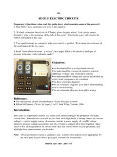
2 It is intwo parts, each part having a value of one weight. Part I studies the Basic Unit, AND gates, ORgates, and binary adders. Part II studies Bistables, flip-flops, memories, and timing devices. Allthese components are available at the Resource Centre. The experiments do not investigate WHYa transistor behaves as it does, but concentrates on WHAT it does. As the circuits studied becomeprogressively more complex, the experiments tend more towards logic than ELECTRONICS Figure Circuit of the Basic UnitFigure modules stack together, and are powered by 5 Volts DC from the power supply. The modulesrefer to a 6 V supply, but they work well at 5 Volts. This guide sheet, in addition to being dividedinto two parts, has a number of sections.
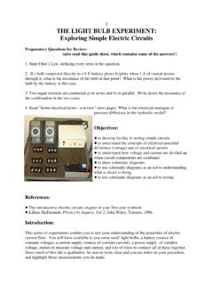
3 When finished one section, turn off the power and removeall wires before going on to the - THE BASIC UNITThe Basic Unit is the simplest blackbox (actually grey) in the experiment. It contains a single n-p-n transistor, with three parallel inputs and two outputs. The circuit diagram is shown in Figure over the Basic Unit and identify the components. The b , c and e stand for the base,collector and emitter of the transistor, and since the emitter is connected to the 0 Volt reference levelfor both the input and output, this circuit is called a common emitter this section we investigate output voltage versusinput voltage. Rather than using a second powersupply for the input voltage, we use a potentiometer asin Figure 2a.
4 Wire up the potentiometer circuit anduse a voltmeter to investigate how it produces avariable ELECTRONICSDIGITAL ELECTRONICSF igure 2b shows the circuit which can beused to show the amplifying properties ofthe transistor. Note that in this figure wehave not detailed the power supply. Inelectronic circuit diagrams the powersupply is usually not shown, and we willcontinue this convention; you may assumethat it is always there, however!Wire the power supply to the left side of the Basic Unit, red-to-red and black-to-black, then turn thesystem on. It is a good idea to keep the power supply on while you are wiring up your circuits. Thisway you can monitor any short circuits that you may encounter.
5 You may measure Vout for variousVin by changing the potentiometer, paying particular attention to the range where Vout changes the potentiometer is set so Vout is Volts, small changes in Vin give large changes in , when the transistor is biased with the potentiometer, it may be used as an amplifier. What would the gain ( = Vout / Vin ) be for your Basic Unit? Why do most non-inverting transistor amplifiers have an even (2,4,6, ..) number of transistors?If high voltage ( Volts) is assigned the value 1, low volts the value 0, then the action of the BasicUnit can be summarized in the following Truth Table:INPUT 1 INPUT 2 OUTPUT 100110001011 0 Verify this table for your Basic Unit. In logic circuits, this truth table defines a NOR gate, symbolized as:(Incidentally, the symbol on the Basic Unit stands for amplifier.)
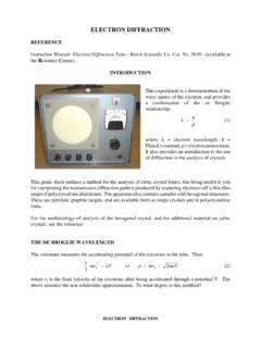
6 DIGITAL ELECTRONICSF igure proceeding to further sections, turn off the power and remove all wires and the potentiometerfrom the Basic Unit so you may make a fresh start on Section - "AND" GATESSet up the circuit shown in Figure 3 using three Basic Units. Inputs 1 and 2 can be just wiresconnected as shown. to make an input high, just plug into any of the sockets marked +6V; to makean input low, plug into any socket marked 0V. Your may turn the boxes over to verify that any +6 Vsocket is indicator lights-up when the input is high, goes out when the input is low. Examine the circuitof the Indicator and explain how it works. Thus the Indicator shows whether the output of the circuitis high or low.
7 (Most of our Indicators have 3 separate lights in one box.)Can you predict the truth table for this configuration? The logic diagram for these three NOR gatesset up like this may help you. Now, measure the truth table for your circuit. In logic circuits, thisdevice is called an AND gate, and is symbolized by : In fact, one of the supplied modules is an AND gate. Verify that the ready-made AND gate has thesame logic as the one you have constructed. Then, turn the AND gate over and trace out its circuitto see - BINARY ADDITIONThe truth table for addition of two one digit binary numbers is:INPUT 1 INPUT 2 CARRYSUM0000100101011110 DIGITAL ELECTRONICSF igure 4. - Binary AdditionThe logic diagram for such a circuit is shown in Figure that this does satisfy the above truth table, and then build it using two Basic Units and anAND gate to prove that it works.
8 This circuit is called a Half - "OR" GATEThis time we only supply the truth table, and challenge you to build the corresponding OR gate. Check your logic by testing your 1 INPUT 2 OUTPUT 1000101011111 The symbol for an OR gate is: Note it is similar but not identical to the symbol for a NOR ELECTRONICSF igure 5. - Full Adder Figure - FULL ADDERSThis section discusses full binary addition, and contains no adder of Section 3 can take two binary digits and add them. But when adding numbers withmore than one bit, provision has to be made for the carry bit too. Such a Full Adder uses two HalfAdders as in Section 3 plus an OR gate, as shown in Figure out the truth table for the Full of two 3-digit binary numbers, A and B, can thus be accomplished as shown in Figure as the AND Gate combined 3 transistors as NOR gates in one box, this circuit could be put inone box too, but the number of transistors is large.
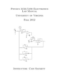
9 (How many?) However, an Integrated Circuitcan be `grown' with this circuitry and end up no larger than the head of a ELECTRONICSF igure 7. - Pin Assignments of 7402 CircuitPART IIINTRODUCTIONThis is a continuation of Part I. Here you investigate more advanced logic Part I the circuits you studied were built up from combinations of simple n-p-n transistors. Mostof your work in Part II will be using integrated circuits ("chips") from the family of Transistor-Transistor-Logic (TTL) will find that whereas the Guide Sheet for Part I tended to be more-or-less explicit as to whatto do, Part II is intended much more as an introduction that will get you thinking about what youwant to do. You will find the references useful in exploring the question of what you wish to learnfrom this circuits must never be driven by more than Volts DC, and will notwork properly at less than volts - THE TTL "NOR" GATEFind the module labelled "7402".
10 This box contains an integrated circuit containing four NOR numbered jacks on the top of the box are wired to the pins on the "chip" in accordance withFigure that three pins are used for each NOR gate in the chip. Also, pin 14 is the +5V power lead forthe circuit, and is also connected to the positive input for the power supply on the side of the , pin 7 is the 0V ground lead and is connected to the other power supply input on the sideof the ELECTRONICSV erify that the logic of the 7402 NOR gate is identical to the Basic Unit using one of the gates in themodule. In Part I you probably assumed (correctly) that any input not connected to anything wouldbe low. This is not correct for TTL circuits. An unconnected input is unpredictable for TTLgates (though the tendency is that unconnected inputs swing "high".)