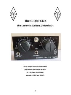
Transcription of A short guide to harmonic filter for QRP transmitter …
1 Title: A short guide to harmonic filters forQRP transmitter : Revd. George Dobbs G3 RJVPage 1of 3 GQRP ClubDatasheetAlthough by their very nature, QRP transmitters radiate less power, the output from such atransmitter does require adequate filtering. Usually to keep the circuit compact, thesetransmitters have a final stage run in Class C and being driven hard with RF power. Of itself,this is a recipe for high harmonic output and a well designed low pass filter is essential. Formany years I have used low pass filters calculated from a series of figures produced by EdWetherhold, W3 NQN, (D * 453 &OXE PHPEHU) and published in two articles in the UK ShortWave Magazine in December 1983 and January Wetherhold has been the ARRL adviser on passive filters for several years and publishedmany fine articles on audio and radio frequency passive filtering.
2 I believe that the two articlesin short Wave Magazine still represent the best source of information for the design of goodlow pass filters for RF articles are comprehensive but here I just want to share enough of the information toenable readers to build useful filters to add to their home made transmitters. There is verylittle mathematics - about 4 pushes of a calculator is the most required to produce informationfor a buildable filter . I will also give a chart for off the shelf low pass filters, which can handleup to 10 watts or RF power, suitable for every HF amateur W3 NQN designs are based upon a seven elements : four capacitors and three are designed for 50 ohms input and output impedance and use standard capacitor is very useful because many calculations and computer programs for filter design givevery odd values of capacitance which have to be made up from series and parallel 1 shows a Seven Element Low Pass filter .
3 Now lets look at some 9 DOXHV Table 1 is a very short extract from a large list of filter parameters in the original W3 NQNarticles. I have taken the practical values for the nine HF amateur bands which have given methe best results over the years. Alongside each band are values for the seven elements in thefilters with values on pF for capacitors and uH for inductors. The characteristics of each filterare described in terms of the ripple cut-off frequency (F-co) and the frequencies of the 3dB (F- 3dB) and 30dB (F - 30dB) attenuation levels. The capacitors are all easy values. I generallyuse polystyrene capacitors for my filter ,QGXFWRUV The inductors are all wound on toroidal cores in the popular Micrometals range. Translating theinductance value to practical inductors is very simple. The formula is given to calculate thenumber of turns. It does require knowledge of the inductance at 10 turns for the required values are given in Table 2.
4 Again I have reduced the W3 NQN information to the 2 mixand 6 mix toroids, the ones that are of most use for this application. The formula is easilyexecuted with a pocket calculator and the resultant figure is rounded to the nearest completenumber of turns. The wire gauge is not critical. Simply use the gauge that will fit well on thecore. The target is to wind an even coil on the core to occupy about three-quarters of theavailable space. If the opposite ends of the winding are too close this will introduce /HYHOV Table 3 shows the smallest core that may be used for particular RF power levels. It isinteresting because for transmitters of 10 watts or less, T37 cores are suitable, making thefilters very compact. Also notice that larger cores are required for the lower frequency again is an extract from the W3 NQN data which used a very conservative maximum ACflux density to determine the minimum core size.
5 So use this table to choose a core suitablefor the required power handling of the Complete Do-It-Yourself Kit .. with just a few simple calculationsRevd. George Dobbs G3 RJVT itle: A short guide to harmonic filters forQRP transmitter : Revd. George Dobbs G3 RJVPage 2of 3 GQRP ClubDatasheet3 UDFWLFDO ([DPSOHV Table 4 gives practical designs for a series of low pass filters over the 9 HF amateur bands fortransmitters of 10 watts power output and less. The constructor simply has to read off thevalues and make up the filters. All of these are filters that I have used to good effect in thepast. Should you require filters for use with higher powers, take the information from thetables to choose a suitable core and work out the appropriate number of turns for that core. Acomplete Do-It-Yourself filter design kit. I keep a range of low pass filters in the shack, eachone mounted in a small tin, for testing purposes.)]
6 So when playing with transmitter circuits, Ihave a low pass filter I can put into use for testing the output. The more frugal constructorcould use such a set of filters for several transmitters and not build filters into each of $%/( 5 HFRPPHQGHG 9 DOXHV%DQG0+]) FR0+]) G%0+]) G%0+]& S)& S)/ X+/ X+ 7 ELEMENT STANDARD VALUE CAPACITOR LOW PASS FILTERSCALCULATING NUMBER OF TURNS REQUIRED ON A TOROID FOR A GIVENINDUCTANCEN = 10 x SQUARE-ROOT ( L / L10) where N = Number turnsL = Required inductance , L10 = Inductance at 10 : A short guide to harmonic filters forQRP transmitter : Revd. George Dobbs G3 RJVPage 3of 3 GQRP ClubDatasheet7$%/( ,1'8&7$1&( $7 78516 )250,&520(7$/6 7252,'6,QGXFWDQFH X+ DW WXUQV &RUH 6L]H 3 UHIL[HV &RUH 0L[ColourT37T44T50T68T80 RangeMHz +Note:1] Inductance values have a tolerance of 5% and are based upon a single layer ] The core prefix gives the nominal outside core diameter in hundredth of an inch3] For example : a T37-2 core has a nominal outside diameter or inches and aninductance of at 10 $%/( 60$//(67 86$%/(7252,'$/ &25()25 28738732:(56'HVLJQDWLRQ RI 6 PDOOHVW 8 VDEOH 7 RURLGDO &RUH 3 RZHU /HYHO 5 DQJH :DWWV 506 &RUHC olour<1010-2525-5050-100100-200 RedT37T44T68T68T80 YellowT37T37T37T44T507$%/( 3 UDFWLFDO([DPSOHV IRU7 UDQVPLWWHUV 8 QGHU ZDWWV 5) 2 XWSXW%DQG0+]& S)& S)/ WXUQV/ WXUQV&RUH.)
7 LUHVZJ 82022003034T50-230 47012002527T37-228 2706801921T37-626 2705601920T37-626 1803901617T37-624 1102701315T37-624 822201214T37-624 1002201213T37-622 561501011T37-622 Note : Wire gauge is not critical. Use size to comfortably fill the core about three-quartersof full circumference. The number of turns has be rounded to the nearest whole numberfrom the calculated value.