Transcription of THERMAL PERFORMANCE MEASUREMENT OF …
1 Transaction on Thermodynamic and heat Transfer ISSN: 2229-8711 Online Publication, June 2011 HT-M12/GJTO Copyright @ 2011/gjto THERMAL PERFORMANCE MEASUREMENT OF heat pipe Patrik Nemec, Alexander aja, Milan Malcho University of ilina, Department of power engineering, Univerzitn 1, Slovakia Email: Received February 2011, Revised March 2011, Accepted March 2011 Abstract: heat pipe is device working on two phase change of working fluid inside. This phase change of working fluid lead to increasing heat transport efficiency of heat pipe . The basic heat pipe working position is vertical position, when the heat pipe can transport maximal heat flow from evaporator to condensator.
2 This article deal about wick heat pipe construction and propose device to identify THERMAL PERFORMANCE . The result of article is comparison of THERMAL PERFORMANCE transported by heat pipe from working positions. Key words: heat pipe , heat transfer, THERMAL PERFORMANCE , capillary structure, experimental MEASUREMENT 1. Introduction Capillary-driven two-phase systems offer significant advantages over traditional single-phase systems. With the typically increased THERMAL capacity associated with the phase change of a working fluid, considerably smaller mass flow rates are required to transport equivalent amounts than in single-phase liquid or gas systems for a given temperature range.
3 Moreover, heat transfer coefficients of two-phase systems are much greater than in single-phase flows and result in enhanced heat transfer. Lower mass flow rates and enhanced THERMAL characteristics provide the benefits of smaller system size (and weight) while providing increased PERFORMANCE . The THERMAL capacity of a single-phase system depends on the temperature change of the working fluid; thus, a large temperature gradient or a high mass flow rate is required to transfer a large amount of heat . However, a two-phase system can provide essentially isothermal operation regardless of variations in the heat load.
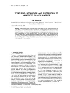
4 Additionally, singlephase systems require the use of mechanical pumps and fans to circulate the working fluid, while capillary-driven two-phase systems have no external power requirements, which make such systems more reliable and free of vibration. The best known capillary-driven two-phase system is the heat pipe , where a schematic of a conventional heat pipe is shown in Fig. 1. The concept of the heat pipe was first presented by [1] and [2], but was not widely publicized until an independent development by [3] at the Los Alamos Scientific Laboratories. heat pipes are passive devices that transport heat from a heat source (evaporator) to a heat sink (condenser) over relatively long distances via the latent heat of vaporization of a working fluid.
5 As shown, a heat pipe generally has three sections: an evaporator section, an adiabatic (or transport) section, and a condenser section. [4]. With evaporator heat addition, the working fluid is evaporated as it absorbs an amount of heat equivalent to the latent heat of vaporization, while in the condenser section, the working fluid vapor is condensed. The mass addition in the vapor core of the evaporator section and mass rejection in the condenser end results in a pressure gradient along the vapor channel which drives the corresponding vapor flow. Return of the liquid to the evaporator from the condenser is provided by the wick structure.
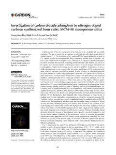
6 As vaporization occurs in the evaporator, the liquid meniscus recedes correspondingly into the wick structure. Similarly, as vapor condenses in the condenser region, the mass addition results in an advanced meniscus. The difference between the capillary radii in the evaporator and condenser ends of the wick structure results in a net pressure difference in the liquid-saturated wick. This pressure difference drives the liquid from the condenser through the wick structure to the evaporator region, thus allowing the overall process to be continuous [4]. Principe of heat pipe [5] Due to the two-phase characteristics, the heat pipe is ideal for transferring heat over long distances with a very small temperature drop and for creating a nearly isothermal surface for temperature stabilization.
7 As the working fluid operates in a thermodynamic saturated state, heat is transported using the latent heat of vaporization instead of sensible heat or conduction where theThermal PERFORMANCE MEASUREMENT of heat pipe Copyright @ 2011/gjto 105 heat pipe then operates in a nearly isothermal condition. This nearly isothermal condition offers benefits of transporting large amounts of heat efficiently, decreasing the overall heat transfer area and saving system weight. The amount of heat that can be transported through the use of latent heat is typically several orders of magnitude greater than transported by sensible heat for a geometrically equivalent system.
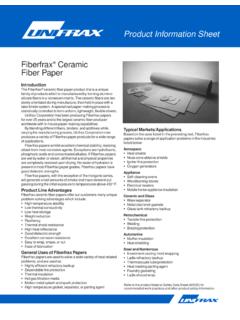
8 Additionally, no mechanical pumping systems are required due to the capillary-driven working fluid. Given the wide range of operating temperatures for working fluids, the high efficiencies, the low relative weights, and the absence of external pumps in heat pipes, these systems are seen as attractive options in a wide range of heat transfer applications [4]. 2. heat pipe construction The major components of a heat pipe are a sealed container, a wick structure, and a working fluid. The wick structure is placed on the inner surface of the heat pipe wall and is saturated with the liquid working and provides the structure to develop the capillary action for liquid returning from the condenser to the evaporator.
9 Return of the liquid to the evaporator from the condenser is provided by wick structure. [6]. heat pipe container The container, working fluid, and wick structure of a heat pipe determine its operational characteristics. One of the most important considerations in choosing the material for the heat pipe container and wick is its compatibility with the working fluid. Degradation of the container or wick and contamination of the working fluid due to chemical reaction can seriously impair heat pipe PERFORMANCE . For example, noncondensable gas created during a chemical reaction eventually can accumulate near the end of the condenser, decreasing the condensation surface area.
10 This reduces the ability of the heat pipe to transfer heat to the external heat sink. The material and geometry of the heat pipe container also must have a high burst strength, low weight, high THERMAL conductivity, and low porosity [7]. Working fluid Using the proper working fluid for a given application is another critical element of proper heat pipe operation. The working fluid must have good THERMAL stability properties at the specified operational temperature and pressure. The operational temperature range of the working fluid has to lie between its triple point and its critical point for liquid to exist in the wicking material.