Transcription of Temposonics - West Coast Plastics
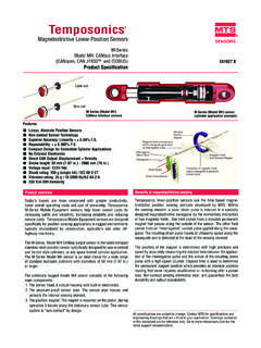
1 SENSORSRT emposonics All specifications are subject to change. Please contact MTS for specifications that are criticalto your benefits of magnetostrictive sensing550919 DMagnetostrictive Linear-Position SensorsE-Series EP2, Analog OutputProduct SpecificationModel EP2 linear-position sensor single-position measurement Linear, absolute measurement Non-contact sensing technology Non-linearity less than Repeatability within Direct position output: Analog 0-10 V EMI shielded and CE certified Measuring range from 4 to 60 inches One year warrantyTemposonics linear-positionsensors use the time-basedmagnetostrictive position sens-ing principle developed by the sensing element, asonic-strain pulse is induced ina specially-designed magne-tostrictive waveguide by themomentary interaction of twomagnetic fields.
2 One field comesfrom a movable permanentmagnet that passes along theoutside of the sensor . The otherfield comes from an interroga-tion current pulse applied alongthe waveguide. The resultingstrain pulse travels at ultrasonicspeed along the waveguide andis detected at the head of thesensing element. The position ofthe magnet is determined withhigh precision and speed by accu-rately measuring the elapsed timebetween the application of theinterrogation pulse and the arrivalof the resulting strain pulse with ahigh speed counter. Using theelapsed time to determine positionof the permanent magnet providesan absolute position reading thatnever needs recalibration or re-homing after a power sensing eliminateswear, and guarantees the bestdurability and output variable:DisplacementResolution:Infinite , restricted by output rippleNon-linearity:< full scale , minimum 90 mRepeatability:< full scaleOutputs:0 - 10 Vdc Controller input resistance RL >5 kOhm Update frequency: > kHz Measuring ranges:4, 6, 9, 12, 15, 18, 21, 24, 30, 36, 42, 48, 54, 60 conditions:Temperature: - 40 to 75 C (- 40 to +167 F) Relative humidity.
3 90% no condensationIngress protection: IP67 Shock test: 50 g (single hit) IEC-Standard 68-2-27 Vibration rating: 5 g/10 - 2000 Hz IEC-Standard 68-2-6 EMC test:Electromagnetic emission: EN 50081-1 Electromagnetic immunity: EN 50082-2EN 61000-4-2/3/4/6 Criteria A, CE qualifiedOperating voltage:+ 24 Vdc nominal (-15% or +20%)Polarity protection: up to -30 VdcOvervoltage protection: up to 36 VdcCurrent drain: 50 - 140 mA (stroke length dependent)Dielectric withstand voltage: 500 Vdc (DC ground to machine ground)Connection type:Integral cable sensor extrusion:AluminumMounting:Adjustable mounting feetMagnet type:Block magnet with stamped metal carrierParametersSpecificationTemposonic s Model EP2 linear-position sensor parametersThere is a new standard of excellence in position sensing.
4 TheTemposonics EP2 sensor establishes new performance standardsfor low-cost, fully-industrial, durable position sensors using thewidely preferred magnetostrictive technology. This principle for accurate and non-contact measurement of linear-position sensing was developed 30 years ago by MTS and isused with outstanding success in a large variety of industrial appli-cations. Industrial applications include harsh environmental condi-tions such as presses, injection molding, tire presses, rolling plants,tunnel driving machines and hydraulic E-Series Model EP2 analog output sensors come withintegrated analog conditioning electronics.
5 The sensor can be con-nected to a control system or indicator directly without the need foran additional interface. The built-in microelectronics produce a con-tinuous voltage output that is proportional to the magnet active measurement stroke range is factory set as shown onpage outputPosition magnetSensing elementActive stroke length(Measuring range)0 V10 V0-10 VTo controller,meter, Sensors Product Specification 550919 D3 Temposonics Model EP2 linear-position sensorConnectionsGreen wireBrown wireWhite wireShieldWiring diagramWire colorSignalGreen0 - 10 VBrown+24V Vdc (-15% / +20%)WhiteDC Ground (0 V)ShieldConnected to sensor housing (Appropriate grounding of cable shield is required.)
6 PVC cable, 5 mm stroke lengths: 4, 6, 9, 12, 15, 18, 21, 24, 30, 36, 42, 48, 54, 60 in. (only)The sensor is fixed onto a flat straight surface of the machine with moveable mounting feet. Apair (2) of mounting feet are provided with each sensor . Additional mounting feet are providedfor measurement stroke ranges greater than 48 inches. These mounting feet slide onto thesensor via channels in the extrusion and should be evenly distributed along its length. Refer tothe drawing on page fastening the mounting feet, 10-32 cap screws are recommended at a maximum torqueof (44 in. lbs.). sensor mountingPosition magnetThe floating magnet (block style L) mounts on the moving machine part and travels justabove the sensor s extrusion.
7 It can be mounted using ferrous metal screws and supportbracket. However, the support bracket can not extend beyond 11 mm ( in.)from thetop of the magnet, unless it is made of non-ferrous magnet should be installed with a perpendicular orientation relative to the top surfaceof the sensor extrusion as shown on page 3. Optimal performance is achieved when thisorientation remains consistent throughout the full measurement stroke magnet, style Lpart no. mm( in.)O mm( in.)6 mm ( in.)31 mm( in.)20 mm ( in.) mm( in.)11 mm ( in.)50 mm ( in.)68 mm( in) mm( in.) mm( in.) in. 4 holes304 mm( in.) mm( in.)
8 Width = mm ( in.)Mounting footStandard mounting footpart no. 400802 MTS Sensors Product Specification 550919 D25 mm( in.) mm( in.)Dead mm ( in.)Null mm ( in.)19 mm( in.)PVC Cable5 m ( ft.)14 mm ( in.)Null positionM4 nutMounting feetMeasurement stroke lengthMountingscrew / nutPosition magnetMounting plate11 mm( in.)3 mm ( in.)27 mm( in.)36 mm( in.)Throughmountingholes (X2)Max. gap3 mm ( 2 mm)( in.) sensor ordering informationUNITED STATESMTS Systems CorporationSensors Division3001 Sheldon DriveCary, NC 27513 Tel: (800) 633-7609 Fax: (919) 677-0200(800) sensor TechnologieGmbH & Co. KGAuf dem Sch ffel 9D - 58513 L denscheidTel: +49 / 23 51 / 95 87-0 Fax: +49 / 23 51 / 56 Sensors TechnologyCorporationUshikubo Aihara-cho, Machida-shiTokyo 194-0211, JapanTel: + 81 (42) 775 / 3838 Fax:+ 81 (42) 775 / Number: 09-06 550919 Revision DMTS and Temposonics are registered trademarks of MTS Systems other trademarks are the property of their respective Temposonics sensors are covered by US patent number 5,545,984.
9 Additional patents are in USA. Copyright 2006 MTS Systems Corporation. All Rights EP2 sensor modelWith an integral cable, analog output (voltage)EP2A -_ _ _Measuring stroke length (inches)004 / 006 / 009 / 012 / 015 / 018 / 021 / 024 / 030 / 036 / 042 / 048 / 054 / 060 Notes: Temposonics Model EP2 sensors include one magnet(part no. 252887), and two mounting feet (part num-ber 400802) for sensors up to 48 inches of strokelength. Additional mounting feet are included for strokelengths over 48 to orderDescriptionFunction/NotesPart no. Mounting feet, standard (spares) Model EP2 sensors come with mounting feet400802 Block style magnet (spare)Style L floating magnet (included with EP2 sensors)252887 Accessories