Transcription of Temposonics - MTS Sensors
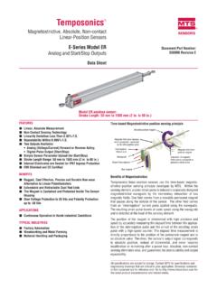
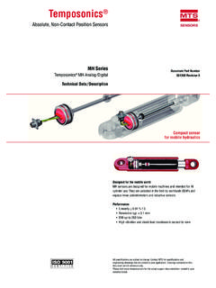
1 Temposonics Magnetostrictive Linear Position SensorsEP / EL AnalogData Sheet For standard applications Position measurement with more than one magnet Ideal for limited installation spaceI 2 ITemposonics EP / EL AnalogData SheetFig. 2: Typical application: Factory automationMEASURING TECHNOLOGYThe absolute, linear position Sensors provided by MTS Sensors rely on the company s proprietary Temposonics magnetostrictive techno-logy, which can determine position with a high level of precision and robustness. Each Temposonics position sensor consists of a ferromagnetic waveguide, a position magnet, a strain pulse converter and supporting electronics. The magnet, connected to the object in motion in the application, generates a magnetic field at its location on the waveguide.
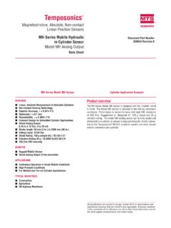
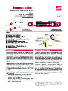
2 A short current pulse is applied to the waveguide. This creates a momentary radial magnetic field and torsional strain on the waveguide. The momentary interaction of the magnetic fields releases a torsional strain pulse that propagates the length of the waveguide. When the ultrasonic wave reaches the end of the waveguide it is con-verted into an electrical signal. Since the speed of the ultrasonic wave in the waveguide is precisely known, the time required to receive the return signal can be converted into a linear position measurement with both high accuracy and 1: Time-of-flight based magnetostrictive position sensing principle4531 Measurement Cycle1 Current pulse generates magnetic fi eld2 Interaction with position magnet fi eld generates torsional strain pulse3 Torsional strain pulse propagates4 Strain pulse detected by converter5 Time-of-fl ight converted into positionSensing element (Waveguide)Position magnet (Magnetic fi eld)Torsional strain pulse converter2EP / EL SENSORR obust, non-contact and wear free, the Temposonics linear position Sensors provide the best durability and precise position measurement feedback in harsh industrial environments.
3 Measurement accuracy is tightly controlled by the quality of the waveguide manufactured exclusively by MTS compact Temposonics EP as well as the ultra low Temposonics EL are profile Sensors suitable for standard applications and in parti-cularly for applications with limited installation space. The evaluation electronics is accomodated in an aluminum sensor housing. Typical fields of applications are plastics industry, metal forming and wood-working as well as factory automation. I 3 ITemposonics EP / EL AnalogData SheetTECHNICAL VDC or VDC, VDC and VDC (controller input resistance RL > 5 k ) mA or mA (minimum / maximum load: 0 / 500 )Measured variablePosition / option: multi-position measurement (2 positions)Measurement parametersResolutionInfiniteCycle timeTyp.
4 Ms < t < 2 ms (depending on stroke lengths)Linearity 1 Magnet slider: % (minimum 60 m), U-magnet: % (minimum 60 m),block magnet: % (minimum 90 m)Repeatability % (minimum 20 m)Operating conditionsOperating temperature +75 C ( +167 F)Humidity90 % rel. humidity, no condensationIngress protection 2,3IP67 (if mating connectors are correctly fitted)Shock test100 g (single shock) IEC standard 60068-2-27 Vibration test15 g / Hz IEC standard 60068-2-6 (resonance frequencies excluded)EMC testElectromagnetic emission according to EN 61000-6-3 Electromagnetic immunity according to EN 61000-6-2 The sensor meets the requirements of the EC directives and is marked with .Magnet movement velocityMagnet slider: 5 m/s; U-magnet: Any; block magnet: AnyDesign / MaterialSensor electronics housingAluminumSensor profileAluminumStroke mm ( in.)
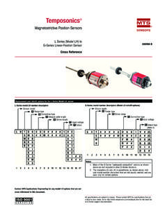
5 Mechanical mountingMounting positionAnyMounting instructionPlease consult the technical drawings and the brief instructions (document number: 551684)Electrical connectionConnection typeM12 (5 pin) male connectorOperating voltage+24 VDC ( 15 / +20 %); UL recognition requires an approved power supply with energy limitation (UL 61010-1), or Class 2 rating according to the National Electrical Code (USA) /Canadian Electrical VPPC urrent mADielectric strength500 VDC (DC ground to machine ground)Polarity protectionUp to 30 VDCO vervoltage protectionUp to 36 VDC1/ Magnet slider # 252 182 and # 252 184, U-magnet # 251 416-2 and block magnet # 403 4482/ The IP rating is not part of the UL recognition3/ The IP rating IP67 is only valid for the sensor electronics housing, as water and dust can get inside the profile I 4 ITemposonics EP / EL AnalogData SheetTECHNICAL DRAWINGCONNECTOR WIRINGM agnetM1250 ( )68 ( ) ( )31( ) ( ) ( )Sensorelectronics ( )13( )
6 Stroke length50 2540(2 100)Dead zone68( )Null zone35( ) 2 ( )*(*)*Start positionMagnet slider S: 19 ( )Magnet slider V: 19 ( )U-magnet OD33: 35 ( )Block magnet L: 35 ( )Mounting clamps5 pin42( ) ( )MagnetM12 Sensorelectronics housing45( )13( ) ( )Stroke length50 2540(2 100)Dead zone68( )17( )27( )2 ( ) ( )68 ( )50 ( )12( )5 pinNull zone35( )*(*)*Start position:Magnet slider S: 19 ( )Magnet slider V: 19 ( )Block magnet L: 35 ( )Mounting ( )D34M12 A-codedPinFunction123451+24 VDC ( 15 / +20 %)2 Output 13DC Ground (0 V)4 Output 25DC GroundControlling design dimensions are in millimeters and measurements in ( ) are in inchesTemposonics EPTemposonics ELI 5 ITemposonics EP / EL AnalogData SheetPosition magnets M520( )43( )14( )40 ( )18 (1)M540 ( )18 57 ( )14 ( ) (1)49 ( ) ( ) ( ) ( ) ( )60 140 3( ) ( ) ( ) ( )33 ( )14( ) ( ) ( )8 2 ( )Distance to sensor elementMagnet slider SPart no.
7 252 182 Magnet slider VPart no. 252 184U-magnet OD33 Part no. 251 416-2 Block magnet LPart no. 403 448 Material: GFK, magnet hard ferriteWeight: Ca. 35 gOperating temperature: +75 C ( +167 F)Material: GFK, magnet hard ferriteWeight: Ca. 35 gOperating temperature: +75 C ( +167 F) Only for: EPMaterial: PA ferrite GF20 Weight: Ca. 11 gOperating temperature: +105 C ( +221 F)Surface pressure: Max. 40 N/mm2 Fastening torque for M4 screws: 1 NmMaterial: Hard ferrite Weight: Ca. 20 gOperating temperature: +75 C ( +167 F) Fastening torque for M4 screws: 1 NmCable connectors 4 Cord sets ~53(~ ) 20( )38( ) 20( )~ 57(~ ) ( )M12 15( ) ( ) ( )4( ) 15( ) ( ) ( )12( ) ( ) ( )M12 1M12 (5 pin) female, straight Part no.
8 370 677M12 (5 pin) female, angledPart no. 370 678M12 (5 pin) female, straightPart no. 370 673M12 (5 pin) female, angledPart no. 370 675 Housing: GD-Zn, Ni / IP67 Termination: Screw; max. mm Contact insert: CuZnOperating temperature: +85 C ( +185 F)Cable : mm ( in.)Fastening torque: NmHousing: GD-Zn, Ni / IP67 Termination: Screw; max. mm2 Contact insert: CuZnOperating temperature: +85 C ( +185 F)Cable : mm ( in.)Fastening torque: 1 NmIngress protection: IP67 Cable: Shielded, pigtail endCable length: 5 m ( ft.)Ingress protection: IP67 Cable: Shielded, pigtail endCable length: 5 m ( ft.)Mounting clamp 4 Holes ( )31 ( )9 ( )50 ( )2 ( )68 ( )10 ( )Mounting clamp width: ( )Mounting clampPart no.
9 403 508 Material: Stainless steel / (AISI 304 / 303)4/ Follow the manufacturer s mounting instructionsControlling design dimensions are in millimeters and measurements in ( ) are in inchesFREQUENTLY ORDERED ACCESSORIES Additional options available in our Accessories Guide 551444I 6 ITemposonics EP / EL AnalogData SheetbDesign0 Without position magnet (order separately)aSensor modelLUltra low profilePCompact profiledConnection typeD34M12 (5 pin) male connectoreOperating voltage1+24 VDC ( 15 / +20 %)cStroke VDC (1 output channel with 1 position magnet) VDC (1 output channel with 1 position magnet) VDC (2 output channels with 2 position magnets) VDC (2 output channels with 2 position magnets) VDC and VDC (2 output channels with 1 position magnet) mA (1 output channel with 1 position magnet) mA (1 output channel with 1 position magnet) mA (2 output channels with 2 position magnets) mA (2 output channels with 2 position magnets)*/ Non standard stroke lengths are available; must be encoded in 5 mm / in.
10 IncrementsDELIVERY sensor 2 mounting clamps up to 1250 mm (50 in.) stroke length + 1 mounting clamp for each 500 mm (20 in.) additional stroke length Accessories have to be ordered stroke length (mm)*Stroke lengthOrdering steps 50 .. 500 mm25 mm50 mmStandard stroke length (in.)*Stroke lengthOrdering steps 2 .. 20 & Software available at: magnets of the same type for multi-position measurement, 2 U-magnets (part no. 251 416-2).UNITED STATESMTS Systems Corporation Sensors Division3001 Sheldon DriveCary, 27513 Phone: +1 919 677-0100E-mail: sensor TechnologieGmbH & Co. KGAuf dem Sch ffel 958513 L denscheidPhone: +49 2351 9587-0E-mail: OfficePhone: +39 030 988 3819E-mail: OfficePhone: +33 1 58 4390-28E-mail: BRITAIN Branch OfficePhone: +44 79 44 15 03 00E-mail: OfficePhone: +86 21 6485 5800 E-mail: OfficePhone: +81 42 707 7710E-mail: Temposonics and Level Plus are registered trademarks of MTS Systems Corporation in the United States; MTS Sensors and the MTS Sensors logo are trademarks of MTS Systems Corporation within the United States.