Transcription of Product Data Sheet - MTS Sensors
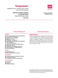
1 Temposonics .. Magnetostrictive, Absolute, Non-contact Sensors . Linear-Position Sensors G- series Models GP and GH Document Part Number Analog (Voltage/Current)/Digital-Pulse Outputs 550959 Revision G. Data Sheet Model GP Profile-style position sensor Model GH Rod-style position sensor FEATURES Time-based Magnetostrictive position sensing principle Linear, Absolute Measurement Movable position magnet Non-Contact Sensing Technology LEDs For Enhanced Sensor Diagnostics Magnetic field encompasses Programmability, Analog Output Models: entire waveguide - generated Voltage or Current, Fully Adjustable Outputs Within: by the interrogation pulse -10 to +10 Vdc or 0 to 20 mA Interrogation Magnetic field from Programmability, Digital-Pulse Output Models: Return wire position magnet PWM or Start/Stop Waveguide Interaction of magnetic Simultaneous Multi-Magnet Measurements Using Start/Stop fields causes waveguide to Strain-Pulse detector generate a strain pulse Linearity Deviation Less Than Repeatability Within Bias magnet Designed for Backward Compatibility with Legacy Temposonics Products Benefits of Magnetostriction Standard 24 Vdc and extended input power supply options for compatibility with older controller interfaces Temposonics linear-position Sensors use the time-based magneto- Integral connector replacement options including: Hanging strictive position sensing principle developed by MTS.
2 Within the (inline) connectors, Adapter cables, Field-installed connector sensing element, a sonic-strain pulse is induced in a specially designed kits magnetostrictive waveguide by the momentary interaction of two magnetic fields. One field comes from a movable permanent magnet BENEFITS that passes along the outside of the sensor. The other field comes from an interrogation current pulse applied along the waveguide. Rugged Industrial Sensor, Backward Compatible with Tempo I, The resulting strain pulse travels at sonic speed along the waveguide Tempo II and L- series Legacy Products and is detected at the head of the sensing element. Compact electronics housing for applications with limited space The position of the magnet is determined with high precision and Offers Supply Options for Compatibility with Older Controller speed by accurately measuring the elapsed time between the applica- Interfaces tion of the interrogation pulse and the arrival of the resulting strain pulse with a high-speed counter.
3 The elapsed time measurement is APPLICATIONS directly proportional to the position of the permanent magnet and is Continuous Operation In Harsh Industrial Conditions an absolute value. Therefore, the sensor's output signal corresponds High Pressure Conditions to absolute position, instead of incremental, and never requires recalibration or re-homing after a power loss. Absolute, non-contact TYPICAL INDUSTRIES sensing eliminates wear, and guarantees the best durability and output repeatability. Fluid Power Lumber and Woodworking Stamping and Diecasting All specifications are subject to change. Contact MTS for specifications and Metalworking, Presses and Assembly Tools engineering drawings that are critical to your application. Drawings contained Material Handling and Packaging in this document are for reference only. Go to for the latest support documentation and related media. Product Overview and Specifications Product overview G- series Sensors feature a microprocessor-based design with enhanced diagnostics and programmability offering the flexibility to fit a wide range of applications.
4 The sensor's head contains the active signal conditioning and a complete integrated electronics interface. Double shield- ing is used to ensure EMI protection for unsurpassed reliability and operating safety. G- series model GH and GP Sensors are extremely robust and are ideal for continuous operation under harsh industrial conditions. Backward compatibility with upgraded performance is one of the pri- mary benefits of choosing a G- series sensor. The G- series sensor provides the same functionality as our legacy Temposonics I, II and L- series sensor products which make it an ideal direct replacement. MTS offers two standard sensor housings, rod and profile extrusion. The rod housing is capable of withstanding high pressures such as those found in hydraulic cylinders. The profile extrusion housing provides convenient mounting options and captive-sliding magnets which utilize slide bearings of special material that reduce friction, and help mitigate dirt build up.
5 Product specifications Parameters Specifications Parameters Specifications OUTPUT ENVIRONMENTAL. Measured output Operating Operating temperature: variables: Position conditions: -40 C (-40 F) to 80 C (176 F). Analog: Infinite (restricted by output ripple) 85 C (185 F) max.. Resolution: Digital Pulse: , and mm +80 C max. for UL Recognition. Contact factory (controller dependent) for high temperature applications. Analog: < 1 ms (typical) Relative humidity: 90% no condensation Update times: Digital (Controller dependent, design reference EMC test: Emissions: IEC/EN 61000-6-3. = (null + stroke+ dead zone) inches x Immunity: IEC/EN 61000-6-2. sec/in. x (number of circulations) IEC/EN 61000-4-2/3/4/5/6/8, level 3/4 criterium A, CE qualified Linearity deviation: Shock rating: 100 g (single hit)/. < stroke (minimum 50 m) IEC standard 68-2-27 (survivability). Repeatability: < full stroke (minimum m) Vibration rating: 15 g (30 g with HVR option)/10 to 2000 Hz, Hysteresis: < 4 m IEC standard 68-2-6 (operational).)
6 Analog Outputs: Voltage (Fully adjustable): WIRING. 0 to 10, 10 to 0, -10 to +10, +10 to -10 Vdc Connection type: 6-pin male D60 (M16) connector, 10-pin MS. (minimum controller load > 5k ohms) style connector, integral cable, or hanging Current (Fully Adjustable): (inline) connectors 4(0) to 20 mA, 20 to 4(0) mA PROFILE STYLE SENSOR (MODEL GP). (Minimum/maximum load, 0/500 ohms). Electronic head: Aluminum housing with diagnostic LED. Digital-Pulse Outputs: display (LEDs located beside connector/cable Start/Stop or exit). Pulse Width Modulation (PWM). Sealing: IP 65**. Stroke Lengths: GP (Profile style): Analog: 50 to 2540 mm (2 to 100 in.) Sensor extrusion: Aluminum (Temposonics profile style). Digital: 50 to 5080 mm (2 to 200 in.) Mounting: Any orientation, adjustable mounting feet or GH (Rod style): T-slot nut (M5 threads) in bottom groove Analog: 50 to 2540 mm (2 to 100 in.) . Magnet types: Captive-sliding magnet or open-ring Digital: 50 to 7620 mm (2 to 300 in.)
7 Magnet Contact factory for stroke lengths longer ROD STYLE SENSOR (MODEL GH). than 2540 mm (100 in.) for Analog outputs Electronic head: Aluminum housing with diagnostic LED. ELECTRONICS display (LEDs located beside connector/cable Operating +24 Vdc nominal: - Vdc standard exit). voltage: +9 to + Vdc optional* Sealing: IP 67 or IP 68 for integral cable models**. Polarity protection: up to -30 Vdc Over voltage protection: Up to 36 Vdc Sensor rod: 304L stainless steel Dielectric withstand voltage: 500 Vdc (DC Operating 350 bar static, 690 bar peak ground to machine ground). pressure: (5000 psi static, 10,000 psi peak). Setpoints: Setpoint adjustment (Null/Span): Mounting: Any orientation. Threaded flange M18 x or 100% of electrical stroke length, 50 mm 3/4 - 16 UNF-3A. (2 in.) min. distance between setpoints. Typical mounting torque: 45 N-m (33 ft. - lbs.). * UL Recognition requires an approved power supply with energy limitation (UL 61010- 1), or Class 2 rating according to the National Electrical Code (USA) / Canadian Magnet types: Ring magnet, open-ring magnet, or magnet Electrical Code.
8 Float ** The IP rating is not part of the UL Recognition. G- series Models GP and GH Temposonics Linear-Position Sensors - Analog/Digital-Pulse Outputs Product Data Sheet , Document Part No.: 550959 Revision G (EN) 09/2015 2 MTS Sensors G- series Models GP and GH Sensors Output Options Output options G- series profile-style and rod-style Sensors are available in analog and digital-pulse outputs. The G- series sensor can also provide a square wave neuter output to support legacy Temposonics I, II, and L- series Product backward compatibility. ANALOG OUTPUTS (VOLTAGE/CURRENT). Active stroke length G- series analog Sensors provide direct signals, including voltage (0. (Measuring range). to 10 Vdc or -10 to +10 Vdc, forward or reverse acting) and current (4 to 20 mA, or 0 to 20 mA, forward or reverse acting). (See Figure 1'). Both voltage and current outputs allow full adjustments of null Output value g Rev ctin ers and span setpoints, (minimum 2 in.)
9 Between setpoints). Since the ardA eA. ctin Forw g outputs are direct, no signal-conditioning elec tronics are needed when interfacing with controllers or meters. Temposonics . G. DIGITAL-PULSE OUTPUTS (START/STOP AND PWM) G- series . G- series digital-pulse Sensors provide either PWM (Pulse Width Dead Modulation) or Start/Stop output signals (see Figure 2'). For zone To controller, meter or Start/Stop, the sensor requires a start signal from a controller or other device: interface module to initiate the measurement cycle. The sensor 0 to 10 Vdc Setpoint 1 Setpoint 2. generates a stop signal at the end of the measurement cycle that is 10 to 0 Vdc (Null) (Span). used to stop the controller's counter clock. -10 to +10 Vdc +10 to -10 Vdc 4 to 20 mA. The elapsed time between the start and stop signals is directly pro- 20 to 4 mA. portional to the magnet's position along the active stroke length. 0 to 20 mA. The controller can calculate the absolute position of the magnet 20 to 0 mA.
10 From the time value and the sensor's unique gradient value, (inverse of the speed for the sonic strain pulse traveling in the Figure 1. Single magnet analog output diagram sensor's waveguide). For PWM output, the elapsed time of the mea- surement cycle is represented as a varying pulse Temposonics width of the output signal. The duration of the . G- series G. pulse is directly proportional to the magnet's . position along the active stroke length. When Pulse width is proportional to magnet position operated in the PWM mode the sensor can be configured for internal interrogations or external PWM To controller, interrogations. Using external interrogations, a + Gate meter, or - Gate other device signal is required from the controller or interface module to initiate every measurement cycle ( Start/Stop Start Pulse same as Start/Stop). When using the mode for Start signal from + Start Input signals internal interrogations, no signal is needed from controller or - Start to sensor interface module.