Transcription of MOUNTING AND MAGNETS (FOR SENSOR …
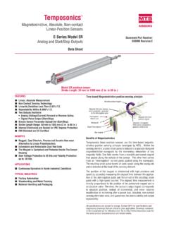
1 MTS Sensors57 Temposonics Linear-Position Sensors Product Catalog 551075 CR and G-Series - MOUNTING and MagnetsSensor hydraulic housingflange with tube becomes apermanent part of the cylinderRing magnetSensor cartridgeelectronic head + SENSOR element,easy to replace in field with screws,(M4 thread, mm hex socket head)When used for direct stroke measurement in fluid cylinders, the sen-sor's stainless steel rod installs into a bore in the piston head/rodassembly as illustrated. This method guarantees a long life and trou-ble-free SENSOR cartridge can be removed from the flange and rod hous-ing while still installed in the cylinder. This procedure allows quickand easy SENSOR cartridge replacement, without the loss of SENSOR MOUNTING (Models RH, GH and GT)Cylinder installationThe position magnet requiresminimum distances away fromferrous metals to allow propersensor output.
2 The minimumdistance from the front of themagnet to the cylinder end capis 15 mm ( in.). The mini-mum distance from the back ofthe magnet to the piston headis provided by the non-ferrousspacer, mm ( in.).Non ferrous spacer> 15 mm ( in.)Ring magnetMin. 3 mm ( in.)Selection of position MAGNETS (must order separately)4 Holeseach 4 mm ( in.) apart on 24 mm ( in.) : mm ( in.) : 33 mm ( in.)Thickness: 8 mm ( in.) : mm ( in.) : 25 mm ( in.)Thickness: 8 mm ( in.)Standard-ring magnetpart no. 201542-2 Floating (open ring) magnet , style Mpart no. 251416-2 magnet spacer(non-ferrous spacer for use with standard ring magnet )part no. 400633 Ring magnetpart no. 400533 : 14 mm ( in.) : 32 mm ( in.)Thickness: 3 mm ( in.)each 4 mm ( in.) apart on 24 mm ( in.)
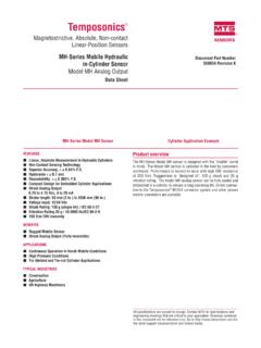
3 HolesMagnets must be ordered separatelywith model RH position standard ring magnet (partnumber 201542-2) is suitable formost applications. 60 25 mm( in.)2 Holeseach 4 mm ( in.) 24 mm ( in.) mm( in.)21 mm( in.) : mm ( in.) : 33 mm ( in.)Thickness: 8 mm ( in.)14 mm ( in.)Min. ID51 mm ( in.)Spherical O. mm ( in.)C53 mm( in.)LSpecific Gravity: : 870 psi max.(Float for use with rod-style sensors in hydraulic fluidor fresh water applications only) magnet float (level sensing applications) part no. 251447 MOUNTING AND MAGNETS (FOR SENSOR MODELS RH, GH AND GT) Temposonics Linear-Position Sensors Product Catalog 551075 CMTS Sensors58R and G-Series - MOUNTING and Magnets5 mm ( in.)T-Slot nut, M5 thread(optional, sold separately)M5 Threadedstud and nutProfile-style SENSOR MOUNTING (Models RP and GP)Flexible installation in any positionTemposonics model RP profile-style sensors offer two basic MOUNTING methods; side groves for use with MOUNTING feet or a bottom grovethat accepts special T-slot nuts.
4 Both the MOUNTING feet and T-slot nuts can be positioned along the SENSOR extrusion to best secure the SENSOR for each particular foot and screwsNote:Model RP and GP sensors include two MOUNTING feet, (part ), for SENSOR stroke lengths up to 1250 mm (50 in.). Oneadditional MOUNTING foot is included for stroke lengths over 1250mm (50 in.) and for each additional 500 mm (20 in.), fastening the MOUNTING feet, 10-32 cap screws are recom-mended at a maximum torque of (44 in. lbs.) Selection of position MAGNETS (included with SENSOR )45 mm( 52 mm( in.)36 mm( in.) mm( in.)Max gap3mm 1mm( in. in.)29 mm( in.)Rotation:Vertical: 18 Horizontal: 360 24 mm( in.)43 mm( in.)14 mm( in.)40 mm( in.)20 mm( in.)Ball-jointed arm,M5 thread18 rotation24 mm( in.)57 mm( in.))
5 14 mm( in.)40 mm( in.)9 mm( in.)Ball-jointed arm,M5 thread 60 25 mm( in.)2 Holeseach 4 mm ( in.) 24 mm ( in.) mm( in.)21 mm( in.) : mm ( in.) : 33 mm ( in.)Thickness: 8 mm ( in.)Captive-sliding magnet , style Vpart no. 252184 Captive-sliding magnet , style Spart no. 252182 Floating (open ring) magnet , style Mpart no. 251416-2A choice of two magnet MOUNTING configurations areavailable with the profile-style SENSOR ; the captive-sliding magnet or the floating (open ring) MAGNETS utilize slide bearings of special material that reduce friction, and if required,help mitigate dirt build up. The slide bearings aredesigned to operate dry, requiring no external lubrication or floating magnet (open ring) mounts on themoving machine part and travels just above the SENSOR s profile extrusion.
6 The open ring magnet (style M) requires a minimum distance away fromferrous metals to allow proper SENSOR output. Itmust be mounted using non-ferrous screws and anon-ferrous support bracket, or utilize a non-ferrousspacer of at least 5 mm ( in.) AND MAGNETS50 mm ( in.)68 mm( in.)9 mm( in.)9 mm( in.) in. 4 holes304 SST28 mm( in.)2 mm( in.)Width = mm ( in.) MOUNTING foot, Standard part no. 400802