Transcription of 6500 Series Programmable Keypad - CORBY …
1 A)B)#C)# #D)# #E)# #F)#1########If the decoder did not POSITION HARNESS:GreyBrownYellowOrangeWhiteGreenB lue6 POSITION HARNESS:RedBlackBlueGreenMUSTIf you do not use this diode,you will have erratic operation and willeventually damage the Keypad and anyother electronic device in the 12 or 24 VDC to the Red (+)and Black (-) wires. Refer tobefore wiring for 24 should hearthree (3) beeps. (You arein programmode) If you did not get 3 beeps, 111111(3beeps)Touch11 222222(3 beeps)Touch11 333333(3 beeps)Touch99(3 beeps)You have now exited the program we'll see if the unit ) Touch 11111 You should hear a keybeep for each number (5 beeps total).After the 5th digit you should hear theMain Relay activate for 2 ) Touch 22222 You should hear theAuxiliary Relay activate for 2 ) Touch 33333 you should receive avoltage output on Switch 3 for 2 you noticed, each code was preceded bya times the isunnecessary, but its usage will always"clear" any previous digits Touch382436you are nowin program mode.
2 Touch25 to the small black jumper on the 2 pinsmarked J1. The pins are next to the 7position wire the above sequence keypads with metal plates the staticgrounding strap must be used. This strapconsists of a ring terminal, disc capacitor,and black wire, and is included with all6500 Series keypads . Connect the wire endof the strap to the negative (-) powersupply connection of the Keypad (the blackwire). Connect the ring terminal end ofthe strap under one of the plate screwsbetween the plate and the wall (see fig. 6).wire is an output for Door-Ajar,Forced Entry, and Time Cancel. Connect amagnetic contact which is closed when thedoor is closed to this wire, and connect theother wire to the negative supply is the Request To Exit (RTE)input trigger. When this wire ismomentarily connected to the common ornegative supply voltage input, the outputsprogrammed to operate from RTE is for Switch 4 which is usedas a voltage output line or printer data voltage output line is capable ofswitching up to 50ma.
3 The output willactivate when an input conditionprogrammed for Switch 4 is is for Switch 3 which is usedas a voltage output line. This voltageoutput line is capable of switching up to50ma. The output will activate when aninput condition programmed for Switch 3is is the common, thewire is the normally open ( ) and thewire is the normally closed ( )contact of the Auxiliary Relay which israted for 1 amp at 30 VDC.(+) positive 12 or 24 VDC supplyvoltage input. This voltage should beuninterrupted and able to supply aminimum of 120ma for the Keypad , and20ma for each LED or night-lite.(-)negative VDC supply voltage are normally closed ( ) andwires are the normally open ( )set of Main Relay contacts. The MainRelay is rated for 5 amps at 30 you use this product to operate a DCdoor strike, magnetic lock, relay, or anydevice that has a coil (inductive load) thatis powered from a DC source; youinstall a diode, in parallel, across the coilterminals.
4 Use a 1N4001, 1N4002 orequivalent. Connect the stripe side of thediode to the coil terminal that becomespositive (+). Connect the other side to theother end of the coil. Proper installation ofthis diode will prevent the high voltagespike that occurs whenever a coil is VDCO perationnowIn order to power this Keypad with a 24 VDC power supply, resistor R3 must to 24 Volts with R3still in place. Your Keypad only has24 VDC capability if you have a 6500series Keypad or program this unit for 24 VDC:Remove circuit board from the keypadCut the metal lead on resistor R3 Connect the 620 ohm resistor (includedin the screw pack for the LEDs) in serieswith the positive (red) lead of the LEDsand the positive side of the light bulb(6522 only).Apply power to the unitDO NOT[[[[If resistors are notinstalled, LEDs will burn PROTECTIONWIRE CONNECTIONSCAUTION !]]]]
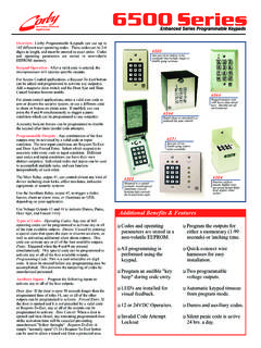
5 !!24 VDC OPERATIONQQQQQQQ6500 Series Programmable KeypadAUX RELAYMAIN J1 SOLID STATESWITCH #450 MA MAX LOADNPNNPNSOLID STATESWITCH #350 MA MAX LOAD6500 Series DecoderFits all 6500 Series KeypadsRelays shown inidle or OFF USED TO CONTROLALARM PANEL OR DOOR STRIKEUSUALLY USED TO RELEASE ANELECTRIC MAGNETIC LOCK12 OR 24 VDC (24 VDC REQUIRESRESISTOR R3 TO BE CUTCONNECT TO POWER SUPPLY (-)ALSO CONNECTS TO METAL PLATER3 NORMALLYCLOSEDIn order to power thiskeypad with a 24 VDCpower supply, resistor R3must be to 24 Volts with R3 still in NOTSPEAKERA beep sounds each time akey is pressed unlesstoggled # to disablethe DOOR CONTACTYELLOWORANGECONNECT TO A MAGNETICCONTACT TO REPORTDOOR AJAR, TIME CANCELOR FORCED TO ACTIVATEADDITIONAL RELAYS,TRIGGER ALARMPANELS, USER CODES12 DELETE A CODE13 CHANGE PROGRAM CODE14 DOOR AJAR INPUT15 FORCED ENTRY INPUT16 PANIC INPUT17 REQUEST-TO-EXIT INPUT18 DISABLE/ENABLE KEY BEEP19 SET CODE LENGTH20 SECURITY LOCKOUT21 SET THE MAIN RELAY TIME22 SET THE AUX RELAY TIME23 SET SWITCH 3 TIME24 SET SWITCH 4 TIME25 ERASE ALL MEMORY26 ERASE CODES ONLY27 SET BUZZER TIME99 EXIT PROGRAM MODET ouch382436to enter program (3))
6 Beeps indicate a valid programcode was entered. Select the options toprogram from the following:The number of code digits entered dependson the code length selected in codes with these outputs:EXAMPLES: Program a code of 54321 toactivate the Main Relay, and trip Switch 3by touching11 5432113 Program a code of 43682 to activate theMain Relay, Aux Relay, and Switch 4 bytouching11 43682124An output does not need to be assigned toactivate the Main Relay : To program a user code of98765 to activate the Main Relay (ONLY)touch11 98765To program a user code of 98765 toactivate the main relay and switch 4 touch11 98765 14 The code to be deleted must be enteredtwice. Any outputs assigned to this codedo not need to be : To delete the code 54321touch12 5432154321 Changes the program code of new program code to beentered must be entered :Place the jumper on J1 Touch382436 Remove Jumper J1 Touch13 (new code) (new code)Finish programming the unitExit program mode by touching99 EXAMPLE: To program a NEW programcode of 123456 Touch13 123456123456 The Outputs listed below are available inany combination for activation from any ofthe four assigned inputs (options 14-1 Door ajar occurs when a door is left openafter a valid entry or exit.)
7 It has a 30second delay past the Main Relay time. Ifthe Main Relay is programmed for anoutput time of 10 seconds, a door ajaralarm will sound in 40 : To assign the door ajar inputto the Auxiliary Relay and the buzzertouch14 25 Forced Entry occurs when the door isopened without a preceding code or : To assign the forced entryinput to the Aux Relay and Switch 4touch15 24A panic condition occurs when theandare touched together. Theand have nokey beep for a silent : To assign the panic input tothe Main Relay and Switch 3 touchA RTE condition occurs when the RTEinput line is shorted to common or : To assign the RTE input tothe Main Relay touch17 1 The beep sounds each time a key isdepressed unless toggled off. This will notdisable the programming option toggles the key beep : To disable the key beep touchSet the code length for 3, 4, 5, or 6 default is 5 digits.
8 The codelength selected applies for all : For 6 digits touch19 6If programmed, this feature can lockoutany Keypad activity for a designated timeafter three consecutive incorrect codeattempts. This feature is active for : Touch20 45 to activatethe security lockout for 45 seconds. Todeactivate this feature, touchPrograms the Main Relay for latching (00)or momentary (01 - 99 seconds) : To program the Main Relayfor 9 seconds touch21 09 , to latch iton/off touch21 00 Programs the Aux Relay for latching (00)or momentary (01 - 99 seconds) : To program the Aux Relay for9 seconds touch22 09 , to latch iton/off touch22 00 Programs Solid-State Switch 3 for latching(00) or momentary (01-99 seconds) : To program Switch 3 for 10seconds touch23 10 , to latch it on/offtouch23 00 Erases any previously programmed optionsand returns to default : To erase memory touch 25 Erases all codes programmed into : To clear all codes touch 26 Allows the Keypad to return "on-line".
9 EXAMPLE: To exit program mode andreturn "on-line" touch99#########Jumper J1 must be removed to performthis )B)#C)D)##E)F)###1 Main Relay3 Switch 32 Aux Relay4 Switch 45 Buzzer################QQQQQQQQQQQQQQQQQQ QQQQQQQQQQQQQQQQQ1 Main Relay3 Switch 32 Aux Relay4 Switch 4##########16 1318 to enable the beep touch1820 00 Programs Solid-State Switch 4 for latching(00) or momentary (01-99 seconds) : To program Switch 4 for 7seconds touch24 07 , to latch it on/offtouch24 00 Programs the Buzzer for latching (00) ormomentary (01 - 99 seconds) : To program Buzzer for 12seconds touch27 12 , to latch it on/offtouch24 007).**The available inputs that can be usedwith the buzzer are door ajar, forced entry,panic and request to exit. The buzzercannot be assigned to a user code. Thebuzzer was introduced in board number6514 and later.
10 **FIG. 1 OPERATE A 12 OR 24 VDC DOOR STRIKE WITH DOOR AJAR AND GREEN & RED LED INDICATORSPROGRAMMING STEPS1)Sets Main Relay timefor 5 )Sets Door Ajar Output tothe Auxiliary )Sets Aux Relay time for2 )Sets the code54321 to activate the Main 54321 will activate the MainRelay. If held open 30 seconds overthe relay time the Aux #142#2202#1154321#1#PROGRAMMING STEPS1)Sets Main Relay timefor 5 )Sets Request-To-Exit tooperate the Main )Sets the code54321 to activate the Main the code 54321 is entered, orRequest-To-Exit is activated, the MainRelay will open the door and changethe LED status from red to #171#1154321#1#PROGRAMMING STEPS1)Sets Main Relay time for5 )Sets Auxiliary Relay timefor 5 )Sets the code98765 to operate the Main Relayand the Auxiliary the code 98765 is entered theMain Relay will open the door andthe Auxiliary Relay will change theLEDs from red to #2205#1198765#12#FIG.