Transcription of LEAD FREE Series LF825Y - Watts Water Technologies
1 ES-F-LF825 YThe FEBCO Series LF825Y Reduced Pressure Zone Assemblies are used to protect against high hazard (toxic) fluids in Water services to industrial plants, hospitals, morgues, mortuaries, and chemical plants. They are also used in irrigation systems, boiler feed, Water lines and other installations requiring maximum pro-tection. The LF825Y features Lead free * construction to comply with Lead free * installation Ultimate mechanical protection of potable Water , against haz-ards of cross-connection contamination. Meets all specifications of AWWA, ASSE, CSA and approved by the Foundation for Cross-Connection Control and Hydraulic Research at the University of Southern California. Approved by the Foundation of Cross-Connection Control and Hydraulic Research at the University of Southern California. Modular relief valve for ease of maintenance. Simple Service procedures. All internal parts serviceable in line.
2 Low head loss. Spring loaded Y type check valves. Internal relief valve pressure sensing passages. Replaceable seat rings on all sizes. End connection NPT ANSI / ASME reduced pressure zone assembly shall consist of two inde-pendently operating, spring loaded, Y pattern check valves and one hydraulically dependent differential relief valve. The assembly shall automatically reduce the pressure in the zone between the check valves to at least 5psi lower than inlet pressure. Should the differential between the upstream and the zone of the unit drop to 2psi, the differential relief valve shall open and maintain the proper valve body and caps including relief valve body and cover shall be Lead free * cast copper silicon alloy. Check valve moving member shall be center stem guided. All hydraulic sens-ing passages shall be internally located within the mainline and relief valve bodies and relief valve cover.
3 Diaphragm to seat area ratio shall be 10:1 minimum. Relief valve shall have a remov-able seat ring. Check valve and relief valve components shall be constructed so they may be serviced without removing the valve body from the line. All seat discs shall be reversible. Shutoff valves and test cocks shall be full ported ball assembly shall be rated to 175psi ( bar) working pres-sure and Water temperature range from 32 F to 140 F (0 C - 60 C). The Lead free * Reduced Pressure Zone Assemblies shall comply with state codes and standards, where applicable, requir-ing reduced lead content. The assembly shall meet the requirements of ASSE Standard 1013; AWWA Standard Code C511; CSA Standard ; and approved by the Foundation for Cross-Connection Control and Hydraulic Hydraulic Research at the University of Southern a flow condition the check valves are open with the pressure between the checks, called the zone, being maintained at least lower than the inlet pressure and the relief valve is main-tained closed.
4 Should abnormal conditions arise under no flow or reversal of flow, the differential relief valve will open and discharge to main-tain the zone at least 2psi lower than the normal flow resumes, the zone s differential pressure will resume and the relief valve will InstallationReduced pressure zone assemblies should be installed with mini-mum clearance of 12" (300mm) between relief valve discharge port and floor or grade. They must be installed where discharge will not be objectionable and can be positively drained away. They should be installed where easily accessible for testing and maintenance and must be protected from freezing. Thermal Water expansion and/or Water hammer downstream of the backflow preventer can cause excessive pressure. Excessive pressure situations should be eliminated to avoid possible damage to the system and assembly. Refer to local codes for specific installation requirements.
5 Some codes may prohibit vertical " Max. (700mm) 12" Min. (300mm)FlowSeries LF825 YReduced Pressure Zone AssembliesSize: 3 4" - 2" LEAD free *LF825 YNOTICEFor Health Hazard ApplicationsJob Name Contractor Job Location Approval Engineer Contractor s No. Approval Representative FEBCO product specifications in customary units and metric are approximate and are provided for reference only. For precise measurements, please contact FEBCO Technical Service. FEBCO reserves the right to change or modify product design, construction, specifications, or materials with-out prior notice and without incurring any obligation to make such changes and modifications on FEBCO products previously or subsequently sold.
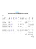
6 * The wetted surface of this product contacted by consumable Water contains less than of lead by PressureMaximum working pressure: 175psi ( bar)Hydrostatic test pressure: 350psi ( bar)Temperature range: 32 F to 140 F (0 C to 60 C)MaterialsMain valve body: Lead free * Cast Copper Silicon AlloyRelief valve body: Lead free * Cast Copper Silicon Alloy Elastomers: Nitrile Seat Discs Diaphragms: Nitrile, fabric reinforcedSprings: Stainless SteelApprovals Standards Approved by the Foundation for Cross-Connection Control and Hydraulic Research at the University of Southern California. AWWA C511 ConformanceCapacityDimensions WeightsSize: 3 4" - 2" SIZEDIMENSIONSWEIGHTAB* 41230573 419731 48331 48341 432473 419731 48331 48341 217432101 226741 211441 4451101 226741 211441 4" kPa psi 138 20 103 15 69 10 34 5 0 5 10 15 20 25 30 gpm 0 19 38 57 76 95 114 lpm 5 10 15 fps mps HEADLOSS1" 11 2" 2" 0 10 20 30 40 50 60 gpm 0 38 76 114 151 190 227 lpm 5 10 15 20 fps
7 Mps 0 20 40 60 80 100 120 gpm 0 76 151 227 304 379 454 lpm 5 10 15 fps mps kPa psi 138 20 103 15 69 10 34 5 kPa psi 138 20 103 15 69 10 34 5 kPa psi 138 20 103 15 69 10 34 5 0 40 80 120 160 200 240 gpm 0 151 304 454 606 760 910 lpm 5 10 15 20 fps mps * B Dimension is less shutoffsWeights shown are approximate.
8 Dimensions shown are nominal, allowance must be made for normal manufacturing information contained herein is not intended to replace the full product installation and safety information available or the experi-ence of a trained product installer. You are required to thoroughly read all installation instructions and product safety information before beginning the installation of this 1622 2016 FEBCOUSA: Tel: (800) 767-1234 Fax: (800) 788-4491 : Tel: (905) 332-4090 Fax: (905) 332-7068 America: (52) 81-1001-8600 Fax: (52) 81-8000-7091 ViewABSide ViewCD