Transcription of INTERNATIONAL JOURNAL OF SCIENTIFIC ... - …
1 INTERNATIONAL JOURNAL OF SCIENTIFIC & TECHNOLOGY RESEARCH VOLUME 5, ISSUE 06, JUNE 2016 ISSN 2277-8616 76 IJSTR 2016 A Charge Controller Design For Solar Power System Nandar Oo, Kyaw Soe Lwin, Hla Myo Tun Abstract: This paper presents the solar charge controller circuit for controlling the overcharging and discharging from solar panel. This circuit regulates the charging of the battery in a solar system by monitoring battery voltage and switching the solar or other power source off when the battery reaches a preset voltage. This circuit is low voltages disconnect circuit. A charge controller circuit can increase battery life by preventing over-charging which can cause loss of electrolyte.
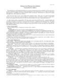
2 The flow chart is also provided. Keywords: Solar panel, a charge controller, battery I. INTRODUCTION Sometimes, electricity can be cut-off due to natural disasters aften happened. So, this type of energy such as wind energy, hydrulic energy and solar energy, they are needed as the source of electricity. Solar energy has become a promising alternative source because it has many advantages such as abundance, pollution free and renewability. The advantages of choosing solar energy by using a solar panel are thet the lifetime of solar panel is long lasting than any other source of energy.
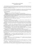
3 The solar charging system is very important and necessary to use for people live in rural areas. The sun is a cheap source of electricity because instead of hydralic generators it uses solar cells to produce electricity. Nowaday, we use the sun as a natural source of energy. Solar resource is umnlimited the government is trying to implement the use of solar panels as energy source in rural and sub urban areas for lighting the street lights, but the battery used to store the power gets affected due to overcharge and discharges. The circuit design of the charge controller The solar power will play and important role in alleviating the energy crisis and reducing the environment pollution and has a bright propspect of applications.
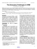
4 A charge controller is an essential part of nearly all power systems the charge batteries, wind, hydro, fuel, or utility grid. Its purpose is to keep the battery properly fed and safe fo long term. Acharge controller is a regulator that goes between the solar panels and the batteries. Regulators for solar systems are designed to keep the batteried charged at peak without overcharging. II. CIRCUIT OPERATION OF CHARGE CONTROLLER DESIGN In my circuit design, during charging, current flows from the solar panel through the diode, MOSFET, fuse F1 and into the battery. Power MOSFET transistor is the main switching device in the charge controller circuit.
5 It connects the solar panel to the battery when it is in need of charging and power is available from the solar panel. Diode is a Schottky device preventing back currents flowing from the battery to the solar panel. Fuse F1 provides a safely limit on the current available from the battery in the event of a short. Comparator U2 is used to control power to the rest of the circuit. When the solar panel voltage is lower than the battery voltage, the rest of the circuitry is disabled. When the solar panel voltage rises above the battery voltage, the output of U2 goes on, switching on transistor which provides power to the rest of the circuit.
6 Resistor networks scale the battery and the solar panel voltages to a range that is useful to U2. Voltage regulator is used as a reference for the battery set points, the reference points are adjusted the resistor network in U1A and U1B. Comparators U1A and U1B monitor the battery voltage and switch states when the battery is fully charged or has dropped to a voltage where charging should resume. The comparators drive as a set-reset flip-flop circuit consisting of U3A and U3B. The output of flip-flop is used to turn the oscillator consisting of U3C and U3D on and off. The flip-flop also drives the two LEDs used to indicate charging or battery full states.
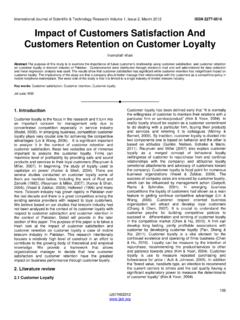
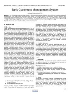
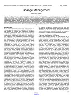
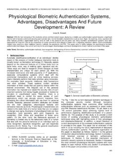
7 The oscillator generates a 10 kHz square wave and the voltage doubler circuit will stepped up the voltage to turn the MOSFET on fully. An equalize switch is included to allow for over-charging of the battery by raising the threshold of the high voltage sensing comparator, forcing the charge current on. flow chart of charge controller INTERNATIONAL JOURNAL OF SCIENTIFIC & TECHNOLOGY RESEARCH VOLUME 5, ISSUE 06, JUNE 2016 ISSN 2277-8616 77 IJSTR 2016 III. CALCULATION AND SIMULATION 1. Calculation for 741 op-amp For Inverting pin, R1=100k , R2=100k , +Vbat=12V (-)vtg= V For Non-inverting pin, When solar panel vtg= 5V, R3=100k , R4=100k (+)vtg= 5= (+)vtg< (-)vtg, <6V, Vout = 0 V When solar panel vtg= 12V, (+)vtg= 12= 6V (+)vtg = (-)vtg, 6V = 6V, Vout = 0 V simulation result when the output at 5V and 12V When solar panel vtg= , (+)vtg= 13= (+)vtg> (-)vtg , > 6V, Vout = V (11V) When solar panel vtg= , (+)vtg= 15= (+)vtg> (-)vtg >6V, Vout = V (11V)
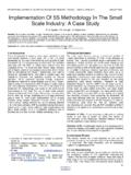
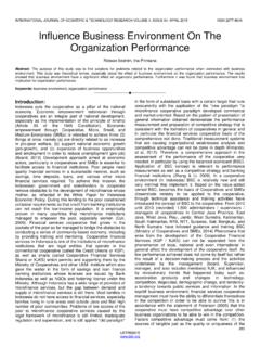
8 Simulation result when the output at and 15V 2. Calculation for battery level comparator At the battery low point, Let battery low level point = 9V For upper comparator, Inverting comparator, Vin, (-) pin = Vref, (+) pin= Vin<Vref, Vout =1 For lower comparator, Non-inverting comparator, Vin,(+) pin= Vref, (-) pin= Vin<Vref, Vout =0 simulation result when the battery level output at low stage= 9V INTERNATIONAL JOURNAL OF SCIENTIFIC & TECHNOLOGY RESEARCH VOLUME 5, ISSUE 06, JUNE 2016 ISSN 2277-8616 78 IJSTR 2016 simulation result of the flip-flop output at low stage= 9V At the battery high point, Let the battery high level point= 13V For upper comparator, Inverting comparator, Vin, (-) pin = Vref, (+) pin= Vin>Vref, Vout =0 For lower comparator, Non-inverting comparator Vin,(+) pin= Vref, (-)
9 Pin= Vin>Vref, Vout =1 simulation result when the battery level output at high stage= 13V simulation result of the flip-flop output at high stage= 13V 3. Calculation for battery level comparator R= 47k , T= = 47k = F= = = 10 kHz 4. Calculation for MOSFET C rate = 70A H The desired current = = 70 =7A The gate voltage =VG The battery voltage =VS The threshold vtg =VT K= = = where, VG = 12V, Vs = 9V VGS= 12 9 = 3V VT = 0V When VS = , VGS = 12 - = ID = k ( ) = ( ) = When VS = 10V , VGS = 12 - 10 =2V ID = k ( ) = ( ) = When VS = 11V , VGS = 12 - 11=1V ID = k ( ) = ( )
10 INTERNATIONAL JOURNAL OF SCIENTIFIC & TECHNOLOGY RESEARCH VOLUME 5, ISSUE 06, JUNE 2016 ISSN 2277-8616 79 IJSTR 2016 =1V When VS = 12V, VGS = 12 - 12=0V ID =0 A IV. CONCLUSION As the solar power system is very advantageous and solar recourse is unlimited of various countries tried to take the use of such recourses but they faced many difficulties in actually implementing the technology. So, every country tried to make to control the battery charging with many types of charge controller design that is low size and cost. The control of battery charging is so important the most manufactures of high quality batteries specify the requirements for voltage regulation, low voltage disconnect and temperature compensation.