Transcription of Military COTS 28V I Filter - Vicor
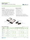
1 M-FIAM9 Rev 1 of 7 06/2017 800 Number M-FIAM9M21* Military cots 28 VIN FilterInput Attenuator ModuleActual x x ,9 x 55,9 x 12,7mmFeatures & Benefits EMI filtering-MIL-STD-461E [1] Transient protection-MIL-STD-704A/E/F, MIL-STD-1275A/B/D Environments-MIL-STD-810, MIL-STD- 202 Environmental stress screening Low profile mounting options Output power up to 500W Output current up to 18A Mini sized package Inrush current limitingProduct HighlightsThe M-FIAM9 is a DC front-end module that provides EMI filtering and transient protection.
2 The M-FIAM9 enables designers using Vicor s 24V or 28V DC-DC converters to meet conducted emission / conducted susceptibility per MIL-STD-461E; and input transients per MIL-STD-704A/E/F and MIL-STD-1275A/B/D. The M-FIAM9 accepts an input voltage of 10 36 VDC and delivers output power up to is housed in an industry standard half brick module measuring x x and depending upon model selected, may be mounted onboard or inboard for height critical Products Maxi, Mini, Micro Series 24V and 28V Input DC-DC converters or VIPAC Arrays [1] EMI performance is subject to a wide variety of external influences such as PCB construction, circuit layout etc.
3 As such, external components in addition to those listed herein may be required in specific instances to gain full compliance to the standards Resistance and CapacityParameter Min Typ Max UnitBaseplate to sink flat, greased surface C/Watt with thermal pad (P/N 20264) C/WattBaseplate to ambient Free convection C/Watt 1000 LFM C/Watt M-FIAM9 M 2 1 Part NumberingMTBF per MIL-HDBK-217F (M-FIAM9M21)Temperature Environment MTBF Unit25 C Ground Benign: 3,582 1,000 Hrs50 C Naval Sheltered: 644 1,000 Hrs65 C Airborne Inhabited Cargo.
4 505 1,000 HrsParameter Rating Unit Notes+IN to IN 36 VDC Continuous 100 VDC 50mS, See 250 VDC 70 SMounting torque 5 ( ) in-lbs 6 each, #4-40 or M3 Pin soldering temperature 500 (260) F( C) <5sec; wave solder 750 (390) F( C) <7sec; hand solderAbsolute Maximum Rating[2] Compatible with SurfMate and InMate socketing system[3] Not intended for socket or Surfmate mountingProductBaseplate 1 = Slotted 2 = Threaded 3 = Thru holeProduct Grade Temperatures ( C)
5 Grade Operating StorageH = 40 to +100 55 to +125M = 55 to +100 65 to +125 Pin Style 1 = Short Pin 2 = Long Pin S = Short ModuMate [2] N = Long ModuMate [2] F = Short RoHS G = Long RoHS K = Extra Long RoHS [3]M-FIAM9 Rev 2 of 7 06/2017 800 Min Typ Max Unit NotesInput voltage 10 28 36 VDC ContinuousInrush limiting A/ F Intended for use in Military Ground Vehicles where the power available is per MIL-STD-1275D.
6 Internal capacitance is ~50 F, which precedes the inrush limit circuit. External precautions should be taken if the source cannot tolerate the capacitive charge current associated with this internal immunity 100 VDC 50ms per MIL-STD-1275A/B/D.
7 Continuous operation 250 VDC 70 s per MIL-STD-1275A/B/D, continuous operation 70 VDC 20ms per MIL-STD-704A, continuous operation 50 VDC per MIL-STD-704E/F, continuous operationINPUT SPECIFICATIONSP arameter Min Typ Max Unit NotesOutput power 500 W See Figures 5 & 6 Output current 18 A Efficiency 96 97 % Internal voltage drop V 500W.
8 25 C baseplateExternal capacitance See Figure 7 on page 5 330 1000 F 50 VOUTPUT SPECIFICATIONSP arameter Min Typ Max Unit NotesON/OFF control Enable (ON) VDC Referenced to VOUT Disable (OFF) VDC 100k internal pull up resistorCONTROL PIN SPECIFICATIONSP arameter Min Typ Max Unit NotesDielectric withstand 1,500 VRMS Input/Output to Base 2.
9 121 VDC Input/Output to BaseSAFETY SPECIFICATIONSS tandard Test Procedure NotesMIL-STD-461E When using with V28 series converters a 27 H inductor is Conducted emissions: CE101, CE102 needed between the Filter and converter for compliance Conducted susceptibility: CS101, CS114, CS115, CS116 below 30% of rated performance is subject to a wide variety of external influences such as PCB construction, circuit layout etc. As such, external components in addition to those listed herein may be required in specific instances to gain full compliance to the standards (Typical at TBP = 25 C, nominal line and 75% load, unless otherwise specified)M-FIAM9 Rev 3 of 7 06/2017 800 Min Typ Max Unit NotesWeight (94) Ounces (grams)
10 Warranty 2 YearsGENERAL SPECIFICATIONSENVIRONMENTAL QUALIFICATIONA ltitudeMIL-STD-810F, Method , Procedure I & II, 40,000ft. and 70,000ft. AtmosphereMIL-STD-810F, Method , Procedure I, Operational. VibrationMIL-STD-810F, Method , Procedure I, Category 14, Sine and Random vibration per Table for Helicopter AH-6J Main Rotor with overall level of for 4 hours per axis. MIL-STD-810F, Method , General Minimum Integrity Curve per Figure with overall level of for 1 hour per , Method , Procedure I, Functional Shock, 40g.