Search results with tag "Power factor"
Understanding Power Factor and How it Affects Your ...
www.progress-energy.comUnderstanding Power Factor Definitions kVA, kVAR, kW, Apparent Power vs. True Power Calculations Measurements Power Factor Correction Capacitors System Impacts I2 R losses, Chapter 9 NEC Equipment sizing Power Factor Charges Problems with adding Caps Harmonic resonance Volt rise Power Factor vs Load Factor
Renewable and Efficient Electric Power Systems
a-ghadimi.com2.3 Power Factor 61 2.4 The Power Triangle and Power Factor Correction 63 2.5 Three-Wire, Single-Phase Residential Wiring 67 2.6 Three-Phase Systems 69 2.6.1 Balanced, Wye-Connected Systems 70 2.6.2 Delta-Connected, Three-Phase Systems 76 2.7 Power Supplies 77 2.7.1 Linear Power Supplies 78 2.7.2 Switching Power Supplies 82 2.8 Power Quality 86

Effective August 2014 SA02607001E passive harmonic ... - Eaton
www.eaton.comPower factor correction: a guide for the plant engineer EATON www .eaton .com Part One: power factor What is power factor? Special electrical requirement of inductive loads Most loads in modern electrical distribution systems are Power factor is the ratio of working power to apparent power inductive .

Reducing Power Factor Cost - Energy
www.energy.govLow power factor is expensive and inefficient. Many utility companies charge you an additional fee if your power factor is less than 0.95. Low power factor also reduces your electrical system’s distribu-tion capacity by increasing current flow and causing voltage drops. This fact sheet describes power

DESIGN OF SINGLE PHASE BOOST POWER FACTOR …
web.wpi.edupower devices is the research of topology structure of power factor correction circuit and integrated circuit of power factor correction. There are several popular chips used to achieve power factor correction, like L4981, UC3842-UC3855A series, KA7534 and TDA4814. [1] Boost circuit is a basic DC-DC conversion circuit.

Introduction to Switch Mode Power Supplies (SMPS)
www.microchip.comPower Factor Correction (PFC) is becoming a government mandated requirement for power supplies in countries around the world. PFC is the process that insures that the input voltages and currents from the AC power line into a power supply are in phase to achieve a “Unity Power Factor”. PFC is very costly to achieve in a linear power supply.

Technical Application Papers No.8 Power factor correction ...
library.e.abb.comPower factor correction and harmonic filtering in electrical plants 3 1 Generalities on power factor correction ... amounts depending on the voltage level of the supply (low, medium or high) and on the power factor. According to the tariff system applied, the consumer
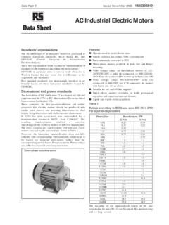
AC Industrial Electric Motors Data Sheet
docs.rs-online.comThe power factor usually being referred to as cos Ø. The power factor is usually between 0.7 and 0.9, however this may vary depending on the motor size and rating. If there are many motors in an installation they will consume a lot of reactive power and will therefore have a lower power factor. Power supply authorities sometimes require the

NCP1654 - Power Factor Controller for Compact and Robust ...
www.onsemi.comPower Factor Controller for Compact and Robust, Continuous Conduction Mode Pre-Converters NCP1654 The NCP1654 is a controller for Continuous Conduction Mode (CCM) Power Factor Correction step−up pre−converters. It controls the power switch conduction time (PWM) in a fixed frequency mode and in dependence on the instantaneous coil current.

PFC MegaPACTM Power Factor Corrected AC-DC …
www.vicorpower.comUG:105 Page 1 PFC MegaPACTM Power Factor Corrected AC-DC Switchers USER GUIDE | UG:105 Overview The PFC MegaPAC family of supplies combine Power Factor Correction (PFC) with the inherent
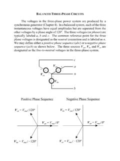
BALANCED THREE-PHASE CIRCUITS
my.ece.msstate.eduThe concepts of power factor and the complex power triangle can also be extended to a balanced three phase power system without loss of generality. The three-phase power factor is defined by the same single-phase equation since the relative angle between the voltage and current is equal in all three phases of a balanced three-phase system.
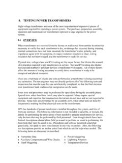
8. TESTING POWER TRANSFORMERS
na.eventscloud.compower Transformers (>1 MVA) be tested with TTR test set. Impedance DC winding resistance Megger and Power Factor windings, bushing and arrestors. Note: Wait until 24 hours after completion of oil filling for Power Factor testing. 13. Load …

1.5KW to 6KW Any Power Combi Pure Sine Wave …
www.sigineer.comLow quiescent current, low power “Power Saving Mode” to conserve energy Automatic Generator Start 4-step intelligent battery charger, PFC (Power Factor Correction) for charger 8 pre-set battery type selector switch plus de-sulphation for totally flat batteries Powerful charge rate of up to 120Amps, selectable from 0%-100%

Topic 5 An Interleaved PFC Preregulator for High-Power ...
www.ti.com5-1 An Interleaving PFC Pre-Regulator for High-Power Converters Michael O’Loughlin, Texas Instruments ABSTRACT In higher power applications, to fully utilize the line, power factor correction (PFC) is a necessity.

Basic Electrical Power Fundamentals
www.fs.fed.usKW is real consumed power turned into heat, and is the product of volts x current x power factor. KVA is apparent power, is always greater than or equal to KW and is the product of volts x amps 1 phase, volts x amps x , √3, 3 phase. USE KVA for calculations unless load is resistive, (ie. unit heaters, furnaces) then KVA = KW.

1606-XLS480E 1606-XLS480EC - Rockwell Automation
literature.rockwellautomation.com* The power factor is the ratio of the true (or real) power to the apparent power in an AC circuit. ** The crest factor is the mathematical ratio of the peak value to RMS value of the input current waveform. Fig. 5-1 Input voltage range Fig. 5-2 Turn-on behavior, definitions n Tu r n-o 85V Ra t e d input range max. 500ms V IN P OUT 60V 300Vac ...

Vienna Rectifier-Based, Three-Phase Power Factor ...
www.ti.comgrid power quality and reduce the harmonic currents drawn, power factor correction is needed as many of the forward loads are DC. For example, in an offboard, fast EV charger, operating at 20 KW, the input is a

Low & Medium Voltage Power Factor Correction Capacitors ...
www.gegridsolutions.comGE supplies Low Voltage and Medium Voltage fixed and automatically switched capacitors for power factor . correction and harmonic mitigation, in the range of 240V through 13.2kV. GE also supplies active filtering equipment and line/load reactors for specific line and load applications.

Electrical System Standards & Design Guidelines
doa.wi.gov28 power, demand, energy, power factor, and frequency. Meter shall be provided with 29 remote monitoring capability to match existing or specified building automation in 30 building. 31 • Power and signal systems shall be provided between buildings as separate manhole and 32 ductbank systems. Spare conduits for each system shall be provided.
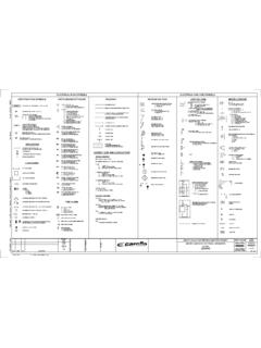
ELECTRICAL PLAN SYMBOLS ELECTRICAL ONE-LINE SYMBOLS ...
www.svwater.commedium voltage disconnect switch non-fused cut out medium voltage disconnecting fuse single fuse cut out medium voltage disconnecting fuse ... pfcc power factor correction capacitor pf power factor pe photocell pcm process control module pcs pvc coated galvanized steel conduit pb pushbutton / pull box

DN-44 UC3854A and UC3854B Advanced Power Factor …
www.ti.com1 Description 2 Specification Differences Application Report SLUA177A– April 1994– Revised December 2005 UC3854A and UC3854B Advanced Power Factor

NCP1632 - Power Factor Controller, Interleaved, 2-Phase
www.onsemi.comPower Factor Controller, Interleaved, 2-Phase NCP1632 The NCP1632 integrates a dual MOSFET driver for interleaved PFC applications. Interleaving consists of paralleling two small stages in lieu of a bigger one, more difficult to design. This approach has several merits like the ease of implementation, the use of smaller

Presentation On Harmonic Filter Design - IEEE Region 5
r5.ieee.orgFeb 03, 2020 · Medium voltage harmonic filters are used on all power systems at all voltage levels, but they are primarily used on industrial power systems at the medium-voltage level where large non-linear loads are in use, to improve power factor, prevent harmonic resonance, and mitigate harmonic distortion.
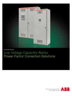
Low Voltage Products Low Voltage Capacitor Banks Power ...
library.e.abb.comCan be factory installed; anti-resonance reactors, filters, fans, blown fuse indication, non-fused, fused disconnect switches and circuit breakers. Low losses Capacitor total losses are less than 0.5 watts per kvar. Auto-bank total losses (without reactors), including accessories such as Power Factor Controller and contactors are less than 1.5
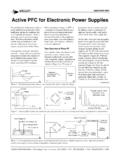
Active PFC for Electronic Power Supplies
www.vicorpower.comcause the problems with the power distribution system. The power factor of the system shown in Figure 2 can be improved slightly by either adding series inductance with

Lecture Notes on Power Electronics - Veer Surendra Sai ...
www.vssut.ac.inwaveforms, Input Line Current Harmonics, Power factor, current distortion and displacement factors- Inverter Mode of Operation. Continuous and discontinuous modes, Effect of source inductance assuming constant load current. ... can be explained as time during which the gate current attains 0.9 ...

Testing and Commissioning of MV/HV Cables
www.idc-online.comcan be performed by means of direct current, power frequency alternating current, or very low frequency alternating current. These sources may be used to performinsulation-withstand tests, and baseline diagnostic tests suchas partial discharge analysis, and power factor or dissipation factor. The selection shall be made after an evaluation of the

Understanding Fault Technical Report
www.nrel.govequipment, power factor improvement equipment, distribution transformers, and service drops. Protecting the EDS and coordinating the components are of utmost importance to an electric utility. When adding DER into the EDS, the system impacts must be understood. Figure 2. Typical electric power system single-line diagram . 2.1 Protective Relaying

Switched Mode Power Supply Specifications Technical Data
literature.rockwellautomation.comy l n O C D V 0 0 9 … 0 6 D3 480 480 W P Power Factor Correction 720 720 W 2 s s a l C C E QN 960 960 W R Redundancy Built-in RH Push-in Terminal, Redundancy built-in RL Spring Terminals, Redundancy built-in RZ Plug / Removable, Redundancy built-in S Output Signal
CHAPTER- 9 HYDRO GENERATOR, CHARACTERISTICS …
www.iitr.ac.inemergency duty imposed on a generator because of power system faults. Sudden short circuit at the generator terminals: A generator should be capable of withstanding, without injury, a 30 second, 3 phase short circuit at its terminals when operating at rated MVA and power factor and at 5% over voltage, with fixed excitation.

Synchronous Generator I - UNLV
www.egr.unlv.eduThe behavior of a synchronous generator varies greatly under load depending on the power factor of the load and on whether the generator is working alone or in parallel with other synchronous generators. Although most of the synchronous generators in the world operate as parts of large power …

A Textbook of Electrical Technology Vol. 2 - Theraja
www.kurratul.weebly.comM. M_F_ or Arnpcrc.turn Mcth0d—Gcncral power Factor Method or Potiet Method—procedural Steps Of Potier Method—Operation of Salient Pole Synchronous Machine— Diagram a Salient Synchronous Calculations from Phasor Diagram—power Developed by a …
VERTIV™ Liebert GXT5
www.vertiv.comDESIGNED FOR HIGH AVAILABILITY • The Unity Power Factor (PF=1.0) ensures the connection of more loads and IT equipment • Device can be swapped during operation without powering down connected equipment thanks to

SUN2000-100KTL-M1 Smart String Inverter
solaravm.comDiagnosis Supported MBUS Supported Fuse Free Design Surge Arresters for DC & AC IP66 Protection ... Adjustable Power Factor Range 0.8 LG ... 0.8 LD Max. Total Harmonic Distortion <3% ... PV-array String Fault Monitoring Yes DC Surge Arrester Type II AC Surge Arrester Type II DC Insulation Resistance Detection Yes Residual Current Monitoring ...
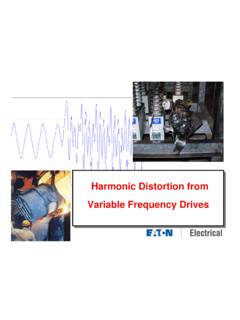
Harmonic Distortion from Variable Frequency Drives
ewh.ieee.orgPower Factor Correction and Harmonics • PFCC’s change the resonant frequency of the distribution system – Depends on the size of the caps and the impedance of the system • Can magnify any existing harmonics Parallel Resonant Frequencies for Various Capacitor Sizes 0 50 100 150 200 250 300 350 400 450 500 0 100 200 300 400 500 600 0 5 10 ...

3 - Phase KVA/KW 50 Hertz 0.8 POWER FACTOR (LAG) AMP …
www.frequencyconverterrental.comTo find the KVA or KW rating (at 0.8PF) for your application, select the 50HZ three phase L-L (line to line) voltage level being utilized. Scan down this column to the current needed for your application (select the next higher current rating for more margin). Scan the row to the left and find the KVA and KW rating needed.

Simulation And Hardware Analysis Of Three Phase …
iosrjournals.orgSimulation And Hardware Analysis Of Three Phase Pwm Rectifier With Power Factor Correction www.iosrjournals.org 29 | Page

Power factor correction: A guide for the plant engineer
www.eaton.comPower factor is the ratio of working power to apparent power . It measures how effectively electrical power is being used . A high power factor signals efficient utilization of electrical power, while a low power factor indicates poor utilization of electrical power . To determine power factor (PF), divide working power (kW) by apparent power ...

Power Factor in Electrical Energy Management
pdhonline.comBenefits of Power Factor Correction Benefit 1 - Reduce Utility Power Bills In areas where a KVA demand clause or some other form of low power factor penalty is incorporated in the electric utility's power rate structure, removing system KVAR improves the power factor, reduce power bills by reducing the KVA. Most utility bills are influenced by

Power Factor Correction - Institution of Engineering and ...
electrical.theiet.orgPower factor correction applied at the origin of the installation consists of a controller monitoring the VAr’s and this controller switches capacitors in or out to maintain the power factor better than a preset limit (typically 0.95). Where ‘bulk’ power factor correction is installed, other loads

Power Factor Improvement
ocw.nthu.edu.twPower Factor Improvement 105 Illustration. To illustrate the power factor improvement by a capacitor, consider a single *phase load taking lagging current I at a power factor cos φ1 as shown in Fig. 6.3. The capacitor C is connected in parallel with the load.

PowerLogic™ PM5300 Series Power and Energy Meter
docs.rs-online.comPower and energy metering 3-phase voltage, current, power, demand, energy, frequency, power factor Multi-tariff 4 4 4 4 Power quality analysis THD, thd, TDD Harmonics, individual (odd) up to 31st 31st 31st 31st I/Os and relays I/Os 2SI/2DO 2SI/2DO 2SI/2DO 2SI/2DO Relays 0 0 2 2 Alarms and control Alarms 35 35 35 35

Power Factor Correction design for On-Board Chargers in ...
www.ti.comPower Factor Correction Design for On-Board Chargers in Electric Vehicles Where ηis the target efficiency for the design which can be better estimated after the first pass design is completed using calculated power loss values to determine the new efficiency and PF is the target power factor for the design

Power Factor and Grid-Connected Photovoltaics
www.gses.com.auPower factor is a measure of the phase difference between the voltage and current in an AC power system. In purely resistive loads (such as an incandescent lightbulb or electric kettle) the current is in phase with the voltage and there is ‘unity’ power factor. Capacitive and inductive
Similar queries
Understanding Power Factor and How, Power factor, Power, Harmonic, Factor, Power factor correction, Eaton, Power factor correction: a guide for the plant engineer EATON www .eaton .com, Introduction to Switch Mode Power, Technical Application Papers No.8 Power factor correction, Power factor correction and harmonic filtering in electrical plants, Voltage, Medium, Motor, PFC MegaPACTM Power Factor Corrected AC, Switchers, Phase, Phase power, Phase power factor, TESTING POWER, Power Factor testing, Generator, An Interleaved PFC Preregulator, High, Pre-Regulator for High-Power Converters, Texas Instruments, 1606, Rockwell Automation, Medium voltage, UC3854B Advanced Power Factor, Harmonic Filter Design, Filters, Active PFC for Electronic Power Supplies, Explained, Testing and Commissioning of MV/HV Cables, Understanding Fault, Transformers, CHAPTER- 9 HYDRO GENERATOR, CHARACTERISTICS, Diagnosis, Insulation, POWER FACTOR (LAG) AMP, Rating, Power factor correction: A guide for the plant engineer, Power Factor Correction Design for On, Board Chargers in Electric Vehicles