Transcription of Katarzyna Krzanowska - City University of New York
1 1. Select the pump speed with the highest efficiency from the pump I chart (figure from your textbook) based on the following conditions. A 1200 m-long (25-cm diameter) pipeline connects two reservoirs with an elevation difference of 32 m. Minor losses include entrance, exit and a glove valve (assume f= ). Determine the discharge, head, and efficiency for the pump. 2 Elev=32m L=1200 D = 1F = Elev=0 212222112122 +++=+++LphzpgVHzpgV V1 = 0 V2 = 0 p1 = 0 p2 = 0 z1 = 0 z2 = 32 m 212 +=LphzH localfrictionLhhh+= gVDLfhhffriction22== gVKgVgVKhhhhvevalveexitentrancelocal2222 22++=++= ++++=++++=vevepKKDLfgVzgVKgVgVKgVDLfzH12 22222222222 V=Q/A +++ +=vepKKDLfgDQzH1422422 Ke = KV = 10 * * *232 QHQHpp+= +++ += From Figure 1: ( , )( , ) Pump speed with the highest efficiency = 3850 rpm Q = L/s Hp = m Pin = hp = * = Pout = QHp = kN/m3 * m3/s * m = kW = 42 % 2.
2 Two identical pumps have the characteristic curves shown in figure The pumps are connected in series and deliver water through a horizontal 15-cm diameter, 1000-m-long steel pipe into a reservoir in which the water level is 25 m above the pump. ( = *10-6 m2/s) Neglect minor losses. (Prob. ). a) Determine the discharge in the system. b) Determine the discharge when the two pumps are connected in parallel. 2 25 m 212222112122 +++=+++LphzpgVHzpgV V1 = 0 V2 = 0 p1 = 0 p2 = 0 z1 = 0 z2 = 25 m 225221242 +=+= gQDLfzhzHLp e = mm e/D = = From Moody diagram Reynolds numbers for flow rates from 1 to 75 L/s are Re = *103 to *105 with corresponding friction factors of to , respectively.
3 Average of friction factor in this interval is Calculations of Hp for different Q s using average value and actual values of f are presented in Table 1. * +=QfHp 1000 mQ 1 Table 1. Flow rate at the system with corresponding total head. Q [L/s] V [m/s] Re f Hp [m] Hp [m] f = 0 0 +00 1 +03 2 +04 5 +04 10 +04 15 +05 20 +05 25 +05 35 +05 40 +05 50 +05 60 +05
4 70 +05 75 +05 Average ( , )( , 30) In the interval of flow rate between 0 to 75 L/s the Total head Hp calculated for average f = and Hp calculated for actual f vs flow rate curves cover together. a) Two pipes in series Q = L/s Hp = m b) Two pipes in parallel Q = L/s Hp = 30 m 3. A pumping station is installed to deliver 10 C water from a reservoir to an elevated storage tank at a minimum required discharge of 300l/sec. The difference in elevations is 15 m, and a 1500-m long, wrought-iron pipe that is 40 cm in diameter is used.
5 Select the pumps from the set given in the figure Determine the discharge and total head at which the pumps operate (Prob. ). 2 Elev=15m 1L=1500 Elev=0D = Qmin = m3/s Pump station 212222112122 +++=+++LphzpgVHzpgV V1 = 0 V2 = 0 p1 = 0 p2 = 0 z1 = 0 z2 = 15 m 225221242 +=+= gQDLfzhzHLp Qmin = 300 L/s = m3/s smvsmDQAQVC26102210* * * === == Q [L/s] Hp [m] 0 50 100 150 200 250 300 350 400 450 500 550 5610* * * vVD e = e/D = From Moody diagram.
6 F = ]4/[ * += 300350( , )( , 114) To satisfy the minimum flow requirement of Qmin = 300 L/s two pumps IV with 3850 rpm in parallel were chosen. Each pump operates at the same flow rate Q = L/s and head Hp = m. The total flow rate and head at which pumps operate is: QT = L/s = m3/s Hp = m Checking results: Because there are two identical pumps in parallel, thus QT = Q1 + Q2 where Q1 = Q2QT = + = L/s Efficiency of each pump that is equal to efficiency of the system: Pin = 114 hp = 114* = kW Pout = QHp = kN/m3 * m3/s * m = 56 .23 kW = 66 % 4. Surf on internet; find out what types of pumps commercially available for pumping water.
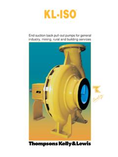
7 Give example. There are two main categories of pumps : 1) Dynamic pumps - operate by developing a high liquid velocity and converting the velocity to pressure in a diffusing flow passage Centrifugal pumps - use an impeller and volute to create the partial vacuum and discharge pressure necessary to move water through the casing. The impeller and volute form the heart of the pump and help determine its flow, pressure and solid handling capability. Axial flow pumps , also called propeller pumps develop most of their pressure by the propelling or lifting action of the vanes on the liquid.
8 These pumps are often used in wet-pit drainage, low-pressure irrigation, and storm-water applications. 2) Positive displacement - operate by forcing a fixed volume of fluid from the inlet pressure section of the pump into the discharge zone of the pump. Reciprocating pumps - a volume of liquid is drawn into the cylinder through the suction valve on the intake stroke and is discharged under positive pressure through the outlet valves on the discharge stroke. Reciprocating pumps are often used for sludge and slurry. Metering pumps - provide precision control of very low flow rates. They are usually used to control additives to the main flow stream.
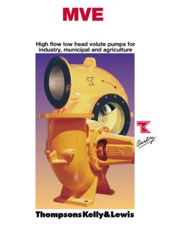
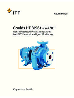
9 Rotary pumps - trap fluid in its closed casing and discharge a smooth flow. They can handle almost any liquid that does not contain hard and abrasive solids, including viscous liquids. The overwhelming majority of contractor pumps use centrifugal pumps . There are three types of centrifugal pumps : 1. Standard centrifugal pumps - provide an economical choice for general purpose dewatering. A number of different sizes are available but the most common model offerings are in the 2 to 4 inch range with flows from 142 to 500 gallons per minute (GPM) and heads in the range of 90 to 115 feet. These pumps should only be used in clear water applications such as agricultural, industrial, and residential.
10 2. High pressure centrifugal pumps are designed for use in applications which required high discharge pressures and flows . Contractors may use them to wash down equipment on the job site as well as install them on water trailers. Other uses include irrigation and as emergency standby pumps in areas where there is a high risk of fire. Typically these pumps will discharge around 100 GPM and produce heads in excess of 240 feet. 3. Trash centrifugal pumps get their name from their ability to handle large amounts of debris and are the preferred choice of contractors and the rental industry.