Transcription of Installation and maintenance - Leroy-Somer
1 E+E-0V110 R220 VOLTOPEN FOR 60 HzSTABPOT and / hElectric Power GenerationInstallation and en -SAFETY MEASURESB efore using your machine for the first time, it is important to read the whole of this Installation and maintenance necessary operations and interventions on this machine must be performed by a qualified technical support service will be pleased to provide any additional information you may various operations described in this manual are accompanied by recommen-dations or symbols to alert the user to potential risks of accidents. It is vital that you understand and take notice of the following warning symbol for an operation capable of damaging or destroying the machine or surrounding equipment. Warning symbol for general danger to personnel. Warning symbol for electrical danger to servicing or repair operations performed on the AVR should be undertaken by personnel trained in the commissioning, servicing and main-tenance of electrical and mechanical components.
2 When the generator is driven at a frequency less than 28 Hz for more than 30 seconds with an analogic regulator, the AC power must be disconnected. WARNINGThis can be incorporated in a machine marked manual is be given to the end user. - We reserve the right to modify the characteristics of its products at any time in order to incorporate the latest technological developments. The information contained in this document may therefore be changed without document may not be reproduced in any form without prior brands and models have been registered and patents applied manual concerns the alternator which you have just wish to draw your attention to the contents of this maintenance / hElectric Power GenerationInstallation and en -CONTENTS1 - SUPPLY .. - SHUNT excitation system ..42 - R220 .. - Characteristics.
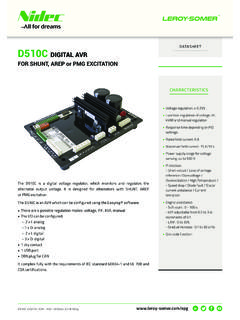
3 - R220 AVR option ..43 - Installation - COMMISSIONING .. - Electrical checks on the AVR .. - Settings .. - Electrical faults ..64 - SPARE PARTS .. - Designation .. - Technical support service ..7 Disposal and recycling instructions WARNINGThe R220 AVR cannot be used in dedicated single-phase 60 R220 is an IP00 product. It must be installed inside a unit so that this unit s cover can provide IP20 minimum total protection (it must only be installed on our alternators in the appropriate location so that when viewed externally, it has a higher degree of protection than IP20). / hElectric Power Generation124 mm 85 mm T1T2T3T4T5T65+ 6- T7T8T9T10T11T12E+E-0V110 R220 P1P2ST3 VOLTOPEN FOR 60 HzSTABPOT 1 KST450 Hz60 HzInstallation and en -1 - - SHUNT excitation system The alternator with Shunt excitation is self-excited with an R220 voltage regulator monitors the exciter excitation current as a function of the alternator output voltage.
4 Very simple in design, the alternator with shunt excitation has no sustaining short-circuit - R220 - Characteristics- Storage : -55 C ; +85 C- Operation : -40 C ; +65 C- Voltage regulation: Voltage supply/sensing range 85 to 139 V (50/60 Hz)- Rapid response time (500 ms) for a transient voltage variation amplitude of 20%- Voltage setting P1- Stability setting Power supply protected by 8 A fuse, slow-blow action (tolerates 10 A for 10 s)The fuse is impregnated in the resin, therefore it can not be Frequency: 50 Hz with ST3 jumper - 60 Hz without ST3 The size of the screwdriver tip used to adjust the potentiometer is - R220 AVR optionPotentiometer for remote voltage adjustment, 1000 / W min: adjustment range 5%.- Remove the ST4 wiring up the external potentiometer; the earth wires must be isolated as well as the potentiometer terminals (wires at the same voltage as the power).
5 SHUNT SYSTEMMAIN FIELDSTATOR : 12 wires (marked T1 to T12)ArmatureFieldVoltageOptionStabilityF requencyPotentiometer for remotevoltage adjustmentVaristor 2 x holes x 109 mm / hElectric Power GenerationInstallation and en -3 - Installation - - Electrical checks on the AVR- Check that all connections have been made properly as shown in the attached wiring Check that the ST3 frequency selection jumper is on the correct frequency Check whether the ST4 jumper or the remote adjustment potentiometer have been - SettingsThe machine is tested and set at the factory. When first used with no load, make sure that the drive speed is correct and stable (see the nameplate). After operational testing, replace all access panels or only possible adjustments to the machine should be made on the - R220 setting (shunt system)Initial potentiometer settings - P1 potentiometer (AVR voltage adjustment): fully Remote voltage adjustment potentiometer: centre the alternator at its rated speed.
6 If the voltage does not increase, the magnetic circuit should be remagnetized (see section ).- Turn the AVR voltage adjustment potentiometer P1 slowly until the output voltage rated value is Adjust the stability setting using P2. Clockwise: increase the rapidity. Anti-clockwise: decrease the - Special type of use Excitation circuit E+, E- must not be left open when the machine is running : AVR damage will - R220 field weakening (SHUNT)The exciter is switched off by disconnecting the AVR power supply (1 wire - 0 or 110V).Contact rating : 16A - 250V power supply contactor must only be closed when the alternator is not being - R220 field forcingBattery must be isolated from the earth. Exciter field may be at line +E-0V110 VOLTPOT 1 KBattery (B Volt) +-t(400V - 10A)DiodeE+E-0V110 Exciter / hElectric Power GenerationInstallation and en - Electrical faultsFaultActionEffectCheck/CauseNo voltage at no load on start-upConnect a new battery of 4 to 12 volts to terminals E- and E+, respecting the polarity, for 2 to 3 secondsThe alternator builds up and its voltage is still correct when the battery is Lack of residual magnetismThe alternator builds up but its voltage does not reach the rated value when the battery is Check the connection of the voltage reference to the AVR- Faulty diodes- Armature short-circuitThe alternator builds up but its voltage disappears when the battery is removed- Faulty AVR- Field windings disconnected- Main field winding open circuit - check the resistanceVoltage too lowCheck the drive speedCorrect speedCheck the AVR connections (AVR may be faulty)
7 - Field windings short-circuited- Rotating diodes burnt out- Main field winding short-circuited - Check the resistance Speed too lowIncrease the drive speed (Do not touch the AVR voltage pot. (P2) before running at the correct speed) Voltage too highAdjust AVR voltage potentiometerAdjustment ineffectiveFaulty AVRV oltage oscillationsAdjust AVR stability potentiometer- Check the speed : possibility of cyclic irregularity - Loose connections- Faulty AVR- Speed too low when on load (or U/F bend set too high)Voltage correct at no load and too low when on load (*)Run at no load and check the voltage between E+ and E- on the AVR- Check the speed (or U/F bend set too high)- Faulty rotating diodes- Short-circuit in the main field. Check the resistance- Faulty exciter armature.(*) Caution : For single-phase operation, check that the sensing wires coming from the AVR are correctly connected to the operating terminalsVoltage disappears during operationCheck the AVR, the surge suppressor, the rotating diodes, and replace any defective componentsThe voltage does not return to the rated Exciter winding open circuit- Faulty exciter armature- Faulty AVR- Main field open circuit or short-circuitedWarning.
8 After operational testing, replace all access panels or / hElectric Power GenerationInstallation and en -4 - SPARE - DesignationDescription 110 RE - Technical support serviceOur technical support service will be pleased to provide any additional information you may all spare parts orders or technical support requests, send your request to or your closest contact, whom you will find at indicating the type and the code number of the ensure correct operation and the safety of our machines, we recommend the use of original manufacturer spare the event of failure to comply with this advice, the manufacturer cannot be held responsible for any / hElectric Power GenerationInstallation and en -Disposal and recycling instructionsWe are committed to limit the environmental impact of our activity.
9 We continuously survey our production processes, material sourcing and products design to improve recyclability and diminish our instructions are for information purposes only. It is the user responsibility to comply with local legislation regarding product disposal and materials Our alternators are mainly built out of iron, steel and copper materials, which can be reclaimed for recycling materials can be reclaimed through a combination of manual dismantling, mechanical separation and melting processes. Our technical support depar-tment can provide detailed directions on products dismounting upon & hazardous materials The following components and materials need a special treatment and need to be separated from the alternator before the recycling process:- electronic materials found in the terminal box, including the Automatic Voltage Regulator (198), Current Transformers (176), interference suppression module (199) and other diode Bridge (343) and Surge suppressor (347), found on the alternator major plastic components, such as the terminal box structure on some products.
10 These components are usually marked with plastic type materials listed above need special treatment to separate waste from reclaimable material and should be handed to specialized disposal oil and grease from the lubrication system should be considered as a hazardous waste and has to be handled according to local / hElectric Power GenerationInstallation and en / hElectric Power GenerationInstallation and en ExtensionOptimizationStart-upOperation Consulting & specification Maintenancecontracts Remanufacturing System upgrade Monitoring System audit Commissioning Training Genuine spare parts Repair servicesOur worldwide service network of over 80 facilities is at your local presence is our guarantee for fast and efficient repair, support and maintenance your alternator maintenance and support to electric power generation experts.