Transcription of Wet Tantalum HI-TMP Capacitors Tantalum Case …
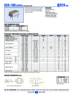
1 Sprague Revision: 22-Sep-20201 Document Number: 40072 For technical questions, contact: DOCUMENT IS SUBJECT TO CHANGE WITHOUT NOTICE. THE PRODUCTS DESCRIBED HEREIN AND THIS DOCUMENTARE SUBJECT TO SPECIFIC DISCLAIMERS, SET FORTH AT Tantalum HI-TMP Capacitors Tantalum Case with Glass-to- Tantalum Hermetic Seal for -55 C to +200 C OperationPERFORMANCE CHARACTERISTICSO perating Temperature: -55 C to +85 C (to +200 C with voltage derating) Capacitance Tolerance: at 120 Hz, +25 C; 20 % standard; 10 %DC Leakage Current (DCL Max.): at +25 C and above: leakage current shall not exceed the values listed in the Standard Ratings Test: Capacitors are capable of withstanding a minimum 500 h life test at a temperature of +200 C at the applicable derated DC working High capacitance Hermetically sealed, Tantalum case +200 C high temperature Terminations: axial, standard tin / lead (SnPb) 100 % tin (RoHS-compliant) available Mounting: through-hole Material categorization: for definitions of compliance please see *This datasheet provides information about parts that are RoHS-compliant and / or parts that are non RoHS-compliant.
2 For example, parts with lead (Pb) terminations are not RoHS-compliant. Please see the information / tables in this datasheet for detailsAPPLICATIONS Industrial Petroleum exploration High temperature / high stress environmentNote Packaging: the use of formed plastic trays for packaging these axial lead components is standard. Tape and reel is not available due to the unit weightNote(1)For insulated parts, add inches [ mm] to the diameter. The insulation shall lap over the ends of the capacitor bodyAvailableAvailableAvailableORDERING INFORMATION134D227X0100K6E3 TYPECAPACITANCECAPACITANCEDC VOLTAGE RATINGCASESTYLE NUMBERRoHS-COMPLIANTTOLERANCEAT +85 CCODEThis is expressed inpicofarads. The firsttwo digits are thesignificant figures. Thethird is the number ofzeros to followX0 = 20 %X9 = 10 %This is expressed in complete the three-digitblock, zeros precede thevoltage rating. A decimalpoint is indicated by an R (6R3 = V)SeeRatingsand CaseCodestableHigh temperature8 = no outerinsulating sleeve6 = hightemperaturefilm insulation(above +125 C)E3 = 100 % tintermination(RoHS-compliant design)Blank = SnPbtermination (standard design)DIMENSIONS in inches [millimeters]CASE CODEDL1 (1)L2 (Max.)
3 EWEIGHT (g)(Max.)TYPE 134 DCLR 79 / 81 [ ] + / - [ + / - ] [ ] [ ] [ ] + / - [ + / - ] [ ] [ ] [ ] + / - [ + / - ] [ ] [ ] [ ] + / - [ + / - ] [ ] [ ] [ ] dia.(No. 22 AWG tinned nickel leads solderable and weldable) Sprague Revision: 22-Sep-20202 Document Number: 40072 For technical questions, contact: DOCUMENT IS SUBJECT TO CHANGE WITHOUT NOTICE. THE PRODUCTS DESCRIBED HEREIN AND THIS DOCUMENTARE SUBJECT TO SPECIFIC DISCLAIMERS, SET FORTH AT Part number definitions:(1) Capacitance tolerance: X9 = 10 %, X0 = 20 %(2) Style number: 8 = no film insulation, 6 = high temperature film insulation(3) Termination: blank = standard tin/lead, E3 = RoHS-compliant 100 % tinSTANDARD RATINGSCAPACITANCEAT 25 C 120 Hz( F) HzESR( )MAX. DCL ( A) , ZAT -25 C ( )MAX. -25 C(%)TYP.
4 CAP. (%)ACRIPPLE85 C40 kHz(mA) RMSPART NUMBERLIFE TESTPERFORMANCE(h AT +200 C)25 C85 C /125 C200 C85 C 125 C 50 VDC AT 85 C; 30 VDC AT 125 C; 30 VDC AT 200 (1)050C(2)(3) (1)050F(2)(3) (1)050T(2)(3) (1)050K(2)(3)50060 VDC AT 85 C; 40 VDC AT 125 C; 36 VDC AT 200 (1)060C(2)(3) (1)060F(2)(3) (1)060T(2)(3) (1)060K(2)(3)50075 VDC AT 85 C; 50 VDC AT 125 C; 45 VDC AT 200 (1)075C(2)(3) (1)075F(2)(3) (1)075T(2)(3) (1)075K(2)(3)500100 VDC AT 85 C; 65 VDC AT 125 C; 60 VDC AT 200 (1)100C(2)(3) (1)100F(2)(3) (1)100T(2)(3) (1)100K(2)(3)1000125 VDC AT 85 C; 85 VDC AT 125 C; 75 VDC AT 200 (1)125C(2)(3) (1)125F(2)(3) (1)125F(2)(3) (1)125T(2)(3) (1)125K(2)(3) Sprague Revision: 22-Sep-20203 Document Number: 40072 For technical questions, contact: DOCUMENT IS SUBJECT TO CHANGE WITHOUT NOTICE. THE PRODUCTS DESCRIBED HEREIN AND THIS DOCUMENTARE SUBJECT TO SPECIFIC DISCLAIMERS, SET FORTH AT In bold and italic: preliminary rating and electrical values.
5 Contact marketing for availability Part number definitions:(1) Capacitance tolerance: X9 = 10 %, X0 = 20 %(2) Style number: 8 = no film insulation, 6 = high temperature film insulation(3) Termination: blank = standard tin / lead, E3 = RoHS compliant 100 % tin(1)This rating withstands 62 VDC at 200 C for 1000 hEXTENDED RATINGSCAPACITANCEAT 25 C 120 Hz( F) HzESR( )MAX. DCL ( A) , ZAT -25 C ( )MAX. -25 C(%)TYP. CAP. (%)ACRIPPLE85 C40 kHz(mA) RMSPART NUMBERLIFE TESTPERFORMANCE(h AT +200 C)25 C85 C /125 C200 C85 C 125 C50 VDC AT 85 C; 30 VDC AT 125 C; 30 VDC AT 200 CCFTK60 VDC AT 85 C; 40 VDC AT 125 C; 36 VDC AT 200 < 12 < 153500134D108(1)060K(2)(3)50075 VDC AT 85 C; 50 VDC AT 125 C; 45 VDC AT 200 (1)075F(2)(3) < 10 < 153500134D757(1)075K(2)(3) < 20 < 253500134D108(1)075K(2)(3)500100 VDC AT 85 C; 65 VDC AT 125 C; 60 VDC AT 200 (1)100T(2)(3) (1)100K(2)(3) (1)100K(2)(3) (1)100K(2)(3) (1)100K(2)(3)500125 VDC AT 85 C; 85 VDC AT 125 C; 75 VDC AT 200 (1)125K(2)(3) (1)125K(2)(3)1000 (1)RIPPLE CURRENT MULTIPLIERS VS.
6 FREQUENCY, TEMPERATURE, AND APPLIED PEAK VOLTAGEFREQUENCYOF APPLIED RIPPLE CURRENT120 Hz 800 Hz 1 kHz10 kHz 40 kHz 100 kHzAMBIENT STILL AIR TEMP. IN C 55 85 105 125 55 85 105 125 55 85 105 125 55 85 105 125 55 85 105 125 55 85 105 125 % of 85 C rated peak voltage100 % - - - - - - - - - - - - 90 % - - - - - - - - - - - - 80 % - - - - - - 70 % - - - - - - 66 2/3 %
7 Sprague Revision: 22-Sep-20204 Document Number: 40072 For technical questions, contact: DOCUMENT IS SUBJECT TO CHANGE WITHOUT NOTICE. THE PRODUCTS DESCRIBED HEREIN AND THIS DOCUMENTARE SUBJECT TO SPECIFIC DISCLAIMERS, SET FORTH AT PERFORMANCE CHARACTERISTICS OF 134D CAPACITORSELECTRICAL CHARACTERISTICSITEMPERFORMANCE CHARACTERISTICSO perating temperature range-55 C to +85 C (to +200 C with voltage derating)Capacitor tolerance 20 %, 10 % at 120 Hz, at +25 CCapacitor change by temperatureLimit per Standard Ratings tableESRL imit per Standard Ratings table, at +25 C, 120 HzImpedanceLimit per Standard Ratings table, at -55 C, 120 HzDCL (leakage current)Limit per Standard Ratings tableAC ripple currentLimit per Standard Ratings table, at +85 C and 40 kHzReverse voltageNoneSurge voltageSurge voltage shall be in accordance with MIL-PRF-39006 and Table 2 of DSCC93026. The DC rated surge voltage is the maximum voltage to which the Capacitors can be subjected under any conditions including transients and peak ripple at the highest line voltage.
8 The DC surge voltage is 115 % of rated DC CHARACTERISTICSITEMPERFORMANCE CHARACTERISTICSLife testingCapacitors shall be capable of withstanding a minimum 500 h life test at a temperature +200 C at derated CHARACTERISTICSITEMCONDITIONCOMMENTSSeal MIL-PRF-39006 When the Capacitors are tested as specified in MIL-PRF-39006, there shall be no evidence of resistanceMIL-PRF-39006 Moisture resistance shall be in accordance with MIL-PRF-39006. Number of cycles: 10 continuous cyclesBarometric pressure (reduced)MIL-STD-202, method 105, condition EAltitude 150 000 feetMECHANICAL CHARACTERISTICSITEMCONDITIONCOMMENTSS hock (specified pulse)MIL-STD-202, method 213, condition I (100 g)The Capacitors shall meet the requirements of , high frequencyMIL-STD-202, method 204, condition D (20 g peak)The Capacitors shall meet the requirements of shockMIL-STD-202, method 107, condition AThermal shock shall be in accordance with MIL-PRF-39006 when tested for 30 , method 208, ANSI/J-STD-002, test ASolderability shall be in accordance with strengthMIL-STD-202, method 211 Terminal strength shall be in accordance with to solder heatMIL-STD-202, method 210, condition CThe Capacitors shall meet the requirements of shall be as specified in MIL-STD-1276.
9 The length and diameter of the terminals shall be as specified in Dimensions table. All terminals shall be permanently secured internally and externally, as applicable. All external joints shall be of Capacitors conforms to method I of MIL-STD-1285 and include capacitance (in F), capacitance tolerance letter, rated voltage, date code, lot symbol, and vishay GUIDEST antalum Selector Comparison Disclaimer Revision: 01-Jan-20191 Document Number: 91000 Disclaimer ALL PRODUCT, PRODUCT SPECIFICATIONS AND DATA ARE SUBJECT TO CHANGE WITHOUT NOTICE TO IMPROVE RELIABILITY, FUNCTION OR DESIGN OR OTHERWISE. vishay Intertechnology, Inc., its affiliates, agents, and employees, and all persons acting on its or their behalf (collectively, vishay ), disclaim any and all liability for any errors, inaccuracies or incompleteness contained in any datasheet or in any other disclosure relating to any makes no warranty, representation or guarantee regarding the suitability of the products for any particular purpose or the continuing production of any product.
10 To the maximum extent permitted by applicable law, vishay disclaims (i) any and all liability arising out of the application or use of any product, (ii) any and all liability, including without limitation special, consequential or incidental damages, and (iii) any and all implied warranties, including warranties of fitness for particular purpose, non-infringement and merchantability. Statements regarding the suitability of products for certain types of applications are based on vishay s knowledge of typical requirements that are often placed on vishay products in generic applications. Such statements are not binding statements about the suitability of products for a particular application. It is the customer s responsibility to validate that a particular product with the properties described in the product specification is suitable for use in a particular application.