Transcription of HWH
1 SERVICE MANUALML37640 Panel Leveling ControlBI-AXIS Hydraulic LevelingFEATURING:HWH CORPORATION(On I-80, Exit 267 South)2096 Moscow Road | Moscow, Iowa 52760Ph: 800/321-3494 (or) 563/724-3396 | Fax: 563 SERIES HYDRAULIC LEVELING SYSTEMHWH TOUCH PANEL-CONTROLLEDR(With or Without Air Dump)RHWH HYDRAULIC LEVELINGUNDERSTAND OPERATOR S MANUAL BEFORE USING. BLOCK FRAME AND TIRESSECURELY BEFORE REMOVING TIRES OR CRAWLING UNDER !STOREOFFONNOT INBRAKEPARK/RCORPORATIONWHHRSECURELY BEFORE REMOVING TIRES OR CRAWLING UNDER OPERATOR S MANUAL BEFORE USING. BLOCK FRAME AND TIRESHWH HYDRAULIC LEVELINGDUMPOFFONSTORECAUTION!BRAKEPARK/ NOT INSECTION TROUBLESHOOTINGGUIDE2 PART FOLDERHOW TO USE MANUALB efore beginning your repair, it is IMPORTANT to read the CAUTIONS and NOTES AND CHECKS in the first section, TROUBLESHOOTING GUIDE. In many cases this will save time and mistakes when trouble shooting a Repair Manual is offered as a guide only.
2 It is impossible to anticipate every problem or combination of problems. Forany problems encountered that are not addressed in this manual, contact HWH Corporation for assistance. (800-321-3494)PROCEED WITH SYSTEM OPERATIONANDGLOSSARYOPERATIONSYSTEMThis manual is written in two sections. Section 1 is System Operation and Trouble Shooting Steps. Section 2 is the Diagrams and Parts Glossary. Begin diagnosis of the system with Section 1. This will give the correct operation and function of the system. The Trouble Shooting Steps are written in order of operation. The Trouble Shooting Steps should be followed in order to avoid improper diagnosis of the system. Section 2 contains diagrams and a parts glossary. Refer to diagrams as directed in the Trouble Shooting Steps. The parts glossary explains the function of individual : Plumbing and wiring diagrams are generic in nature.
3 Refer to specific owner s manuals when availableor contact HWH Corporation for specific diagrams when !BLOCK FRAME AND TIRES SECURELY BEFORE CRAWLING UNDER VEHICLE. DO NOT USE THE LEVELINGJACKS OR AIR SUSPENSION TO SUPPORT VEHICLE WHILE UNDER VEHICLE OR CHANGING TIRES. VEHICLEMAY DROP AND OR MOVE FORWARD OR BACKWARD WITHOUT WARNING CAUSING INJURY OR ROUTING OR REROUTING HYDRAULIC HOSES AND WIRES, BE SURE THEY ARE NOT EXPOSED TO ENGINEEXHAUST OR ANY HIGH TEMPERATURE COMPONENTS OF THE PLACE HAND OR OTHER PARTS OF THE BODY NEAR HYDRAULIC LEAKS. OIL MAY CUT AND PENETRATE THE SKIN CAUSING INJURY OR CLASSES ARE TO BE WORN TO PROTECT EYES FROM DIRT, METAL CHIPS, OIL LEAKS, ECT. FOLLOWALL OTHER SHOP SAFETY AND CHECKSRead and check before proceeding with Trouble Shooting : HWH CORPORATION ASSUMES NO LIABILITYFOR DAMAGES OR INJURIES RESULTING FROM THEINSTALLATION OR REPAIR OF THIS If the jacks cannot be retracted, see TROUBLE SHOOTING PART 15 Step 2 for temporary measures.
4 Make sure the manual retract valves are closed before trouble The Trouble Shooting Guide must be followed in order. Problems checked for in one step are assumed correct and may not be checked again in following position. If the vehicle is equipped with HWH room4. Most coaches have more than one battery; one for the engineand the other(s) for the coach. The engine battery suppliespower for the control box and hydraulic pump. Batteries underno load should read volts. Batteries must maintain good6. Do not replace the control box unless the Repair Steps sayto replace it. Otherwise the malfunctions may damage thenew control Proper grounding of all components is critical. See the electrical circuit for specific grounds required. Faulty grounds,especially for the control box, solenoid manifold or the pumpassembly, may cause control box component damage and /orimproper or erratic manual is intended for use by experienced mechanicswith knowledge of hydraulic and automotive electricalsystems.
5 People with little or no experience with HWHleveling systems should contact HWH technical service(800-321-3494) before beginning. Special attention shouldbe given to all cautions, wiring, and hydraulic note: When installing a new control box, makesure the box is properly grounded before applying powerto the tools for trouble shooting the HWH leveling systems:JUMPER WIRES (UP TO 10 GAUGE)PRESSURE GAUGE (3500 PSI MIN.)MULTI-METER12 VOLT TEST LIGHTPROCEED WITH THE TROUBLESHOOTING STEPS ON THEFOLLOWING PAGE3. Check that the oil reservoir is full with the jacks in the fullyvoltage under load. Batteries must be in good condition withno weak cells. An alternator, converter or battery charger willnot supply enough power for the system to operate hose end, tighten the hose end to snug plus 1/4tighten the hose end 1/3 turn (2 FLATS). If tightening anmake the hose end snug (finger tight) on the fitting, thenTightening of hose ends: If tightening a new hose end,turn (1 FLAT).
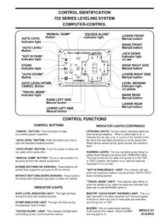
6 Extensions, refer to the HWH Owners Manual for properposition of the room when checking the oil "OFF" (I) BUTTON:"STORE" BUTTON:"STORE" button. This button is used to automatically retractthe DOWN LIGHTS:"NOT IN PARK/BRAKE" LIGHT:when the hand/auto brake is not set and the "LEVEL"MASTER "JACKS DOWN" WARNING LIGHT:light mounted in the dash separate from the touch panel. and the ignition is "ON".BUZZER:CONTROL FUNCTIONSCONTROL BUTTONSPush the "OFF" button to stop hydraulicThe store indicator light is above theThis indicator will light This is a This is a jacks down warning. It will sound if theEXTEND BUTTONS (UP ARROWS):RETRACT BUTTONS (DOWN ARROWS):LEVELING LIGHTS:These buttons will extend their respective jack pairs to lift the buttonswill retract their respective jack pairs to lower the four yellow indicating lights are level sensing indicators. When a yellow light is on, it indicates that its side, end, or corner of the vehicle is low.
7 No more than two lights should be on at the same is the on button for the levelingThe four red lights surrounding the yellow level indicators are jacks down WARNING lights. They are functional only when the ignition is in the "ON" extended 1/4 to 1/2 The on indicator light is above the (I) "JACKS DOWN" warning light is on. CONTROL IDENTIFICATION325 SERIES LEVELING SYSTEMTOUCH PANEL-CONTROLor "ACC" position, the system is on, and the jacks areIt will be on when any one or more jacks are extended button is being LIGHTSHYDRAULIC OPERATIONS (I) LIGHT: This light indicatesthat the panel is LIGHT:This light indicates that the systemis in STORE HYDRAULIC LEVELINGUNDERSTAND OPERATOR S MANUAL BEFORE USING. BLOCK FRAME AND TIRESSECURELY BEFORE REMOVING TIRES OR CRAWLING UNDER VEHICLE."DUMP" BUTTON"STORE" BUTTON"OFF" BUTTONLEFT SIDE RETRACTLEFT SIDE EXTENDPOWER ON LIGHTBUTTON"ON" BUTTONSTORE LIGHTBUTTONONOFFDUMPSTORECAUTION!
8 NOT INPARK/BRAKELEVEL LIGHTS (4-Yellow)REAR RETRACT BUTTONREAR EXTEND BUTTONRIGHT SIDE EXTEND BUTTONRIGHT SIDE RETRACT BUTTONFRONT RETRACT BUTTONFRONT EXTEND BUTTONWARNING LIGHTS (4-Red)DUMP BUTTON:(IF APPLICABLE) This button will dumpthe air from the vehicle OPERATIONThe 325 leveling system is a manually controlled, BI-AXIS push-button system. This system will always extend two [2] jacks at the same time, both front jacks, the left front and the left rear jacks, the right front and right rear jacks or both rear jacks. The jacks are controlled by the UP and DOWN arrow buttons on the right hand side of the touch panel. The UP arrows extend jack pairs and the DOWN arrows retract jack are two parts to leveling a vehicle. First the vehicle is leveled. The jacks are used to turn all the yellow level indicators off. The second part of leveling is to stabilize the vehicle.
9 This is accomplished by extending any jacks not used for leveling to the ground and lifting the vehicle about to 1 ignition must be in the "ON" or "ACC." position and the park brake must be set to turn the system on. The "NOT IN PARK/BRAKE" indicator light will come on while the "ON" button is being pushed if the park brake signal is not present. The system will not turn UP and DOWN arrows will function. The "DUMP" button will function at this the "ON" (I) button will turn the system on. The POWER ON light should be lit. With the POWER ON light on, If the vehicle is equipped with an air suspension, the air must be exhausted from the suspension before leveling the vehicle. If the air is not exhausted, the suspension height control valves will interfere with the leveling procedure. There are two types of air dump systems that HWH controls. One system uses air solenoid valves supplied by HWH.
10 The second system is supplied by the chassis manufacturer. This is a pilot air dump system. The HWH touch panel has a "DUMP" button. The "DUMP" button will only work if the POWER ON light is on. If the vehicle uses the HWH air dump pilot air dump system is used, the engine may be on or off. The "DUMP" button can be pushed and released. The pilot air dump system will return to the travel position if the ignition is on and the "STORE" button is pushed or the park brake is : Releasing the park brake to return the suspension to travel mode (vehicle to ride height) is not recommended for normal operation. This is a fail safe if the "STORE" button is not used to retract the jacks. MANUAL LEVELING OPERATIONOn the right hand side of the touch panel there are four (4) red and four (4) yellow indicator lights. The four red indicator lights are JACK DOWN warning lights. There is one light for each jack.