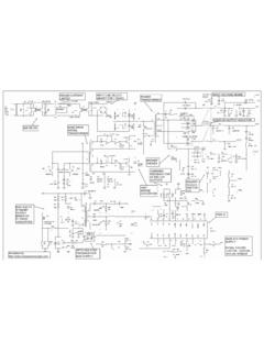
Transcription of Build a nixie power supply - LEDsales
1 Build a nixie power supplyTo drive nixie tubes or neon lamps you need a DC power supply ofaround 170 volts for consistent and fast tube striking. But where to getsuch a supply ? This simple switchmode converter provides the requiredvoltage with enough current to supply most kit allows you to make a very sim-ple switchmode boost (step-up) con-verter for powering nixie tubes and simi-lar displays that require voltages between100 and 200 Volt DC. It uses very readilyavailable parts which can be bought fromalmost any electronics components storeshould the need arise for it worksThe circuit is designed around one ofthe most common ICs on the planet the555 timer chip.
2 While several decades old,this chip still finds uses in a great manyareas, including simple converters likethis 555 is configured as an astable os-cillator which oscillates at a frequency(around 45kHz) determined by resistorsR1 and R2, and capacitor C2. The 555 soutput directly drives a high voltageMOSFET, Q1, that switches the currentthrough an inductor, the FET is on, current flows fromV+ through the inductor to ground. Asthe current in the inductor builds up, theFET then turns the FET turns off, the currentflowing through the inductor tries to con-tinue to flow but can t flow through theFET, so the voltage on the FET s drainterminal rises until the ultrafast diode, D1becomes forward biased.
3 This allows theenergy contained in the coil to be dumpedinto the high voltage capacitor, cycle continues until the voltageacross C4 reaches a value set by trimpotVR1. R4, R5 and VR1 form the feedbackdivider for the circuit, and are chosen suchthat the voltage across C4 is divided downto around volts. This voltage is appliedto transistor Q2, a BC547. When the volt-age across C4 rises to the point where thevoltage from the divider is enough to turnQ2 on, then Q2 pulls down the Control pinof the 555, stopping it from oscillating andshutting down the soon as this happens, the voltageacross C4 begins to fall, as does the volt-age into the base of Q2, and so Q2 turnsoff, allowing the converter to restart.
4 Thisis how the circuit regulates the voltage,and in practice it works quite R6 and capacitor C3 form a sim-ple snubber network, while C1 is the mainreservoir cap for the circuit. And that sabout all there is to it!Building itWell, there is not much to say here, justget the components in their appropriateplaces and the right way around (for thepolarised components like the diode, elec-trolytic capacitors, transistors and IC) andsolder them into place. Make sure thereare no shorts between IC pins or otherplaces on the board. When you havechecked and double checked your work,you can then give the unit a smoke testPlace the board on an insulating sur-face (clean, dry wood or plastic is fine)The circuit diagram for the switchmode board and overlay shown larger than actual listPart #Value/descriptionU1555 timerQ1 IRF740Q2BC547D1UF4004C1330uF trimpotL1100uHTB1, TB22-way terminal blockSOC18 pin IC socketPCB1 Circuit boardHigh voltage labeland, after making sure the trimpot is cen-tred, connect a 9 to 12 volt DC source tothe input terminal block.
5 It is best to use acurrent limited supply to start with, in casethere is a problem. Do not connect thecircuit to a battery or other high currentsupply without having tested it first!Now, take your multimeter and checkthe output voltage. It could be anywherebetween 100 and 200 Volt DC. If there isno voltage on the output, check that the555 is oscillating (you do have a logicprobe of course!). If not, find the problemand fix you get a high voltage output,make sure it is adjustable from around 100volts to 200 volts. The lower limit variessomewhat with different components, oneprototype couldn t be adjusted below that, as the kit is supplied with a400 volt MOSFET, the output can exceed200 volts, but don t use the kit for voltagesabove final test involves connecting aload to the supply , such as a nixie tubevia a 22k resistor.
6 If the supply drives theload, then you re in business! Of course,turn the supply off and allow the voltageto drop to a safe level before making anyconnections!Note that the voltage will vary a bit withload, but it should not swing by more thana few volts from 0 to 10mA !This circuit, while not as danger-ous as mains power , providesenough energy to potential kill aperson should they be connectedbetween the high voltage outputand ground in the right way, sobe careful when working on thiscircuit!Always, turn off the power andwait for the high voltage output todrop before making any changesto the completed, the circuitmust be mounted inside an insu-lated case with properly insulatedterminals to prevent anyone ac-cidentally coming into contactwith the high voltage output!
7 Identifying the parts of your power supply kitThe following guide should help you to identify the parts and assemble it (2n2) capacitor will be marked 2n2 or 222. The 100pF capacitor is the small light grey one with theorange or black top. Neither of these are polarised and can be installed either way 330uF and electrolytic capacitors are larger black barrel diodes and are clearly marked. They arepolarised and must be installed the correct way around. The longer lead is positive, or if both leads are thesame, the negative is clearly marked with a big line or minus symbol running down the side of the coloured bands represent numbers and multipliers as shown in thetable.
8 Some resistors have four bands (two digits, a multiplier band and atolerance band) while some resistors have five bands. Five-band resistors areread in the same manner as four-band resistors, except that the first threebands are digits, the fourth a multiplier and the fifth the tolerance bandsruoloCsderdnuHsneTstinUreilpitluMec nareloTkcalB0001%02nworB11101%1deR222001 %2egnarO3330001 wolleY444000,01 neerG555000,001 eulB666000,000,1 teloiV777 yerG888 etihW999 dloG FETThe FET will be marked IRF740. Note that the FET must be installed the correct way around, withthe back of the device facing towards the D SDiodeThe UF4004 will be marked UF4004.
9 Note that other similar diodes may be substituted. They willwork fine in this kit. It will be black with silver 1 amp fast diode isusually black (the end withthe stripe)The 555 timerThis is the 8 pin device. Note that it must be installed the correct way around. Pin 1 is marked witha small dot, and the pin 1 end of the chip will have a semicircular notch or mark. The IC socket alsohas this notch, so make sure it is installed the correct way around also, as this notch is used toindicate device 100uH inductor is similar in size and shape to the 330uF capacitor, but it has no markings. It is not polarised, socan be fitted either way around.