Transcription of High Speed Infrared Emitting Diode, 940 nm, …
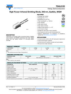
1 Semiconductors Rev. , 13-Jan-171 Document Number: 81931 For technical questions, contact: DOCUMENT IS SUBJECT TO CHANGE WITHOUT NOTICE. THE PRODUCTS DESCRIBED HEREIN AND THIS DOCUMENTARE SUBJECT TO SPECIFIC DISCLAIMERS, SET FORTH AT Speed Infrared Emitting diode , 940 nm , GaAlAs, MQWDESCRIPTIONVSLB3940 is a high Speed Infrared Emitting diode in GaAlAs, MQW technology, molded in a clear plastic Package type: leaded Package form: T-1, clear epoxy Dimensions: 3 mm Peak wavelength: p = 940 nm high Speed high radiant power high radiant intensity Angle of half intensity: = 22 Low forward voltage Suitable for high pulse current operation Good spectral matching to Si photodetectors Material categorization: for definitions of compliance please see Infrared remote control units Free air transmission systems Infrared source for optical counters and card readersNote Test conditions see table Basic Characteristics Note MOQ: minimum order quantity94 8636 PRODUCT SUMMARYCOMPONENTIe (mW/sr) (deg) p (nm)tr (ns)VSLB394065 2294015 ORDERING INFORMATIONORDERING CODEPACKAGINGREMARKSPACKAGE FORMVSLB3940 BulkMOQ: 5000 pcs, 5000 pcs/bulkT-1 VSLB3940-MSZA mmopackMOQ: 10 000 pcs, 2000 pcs/boxT-1 VSLB3940-QS21 Tape and reelMOQ.
2 10 000 pcs, 2000 pcs/reelT-1 ABSOLUTE MAXIMUM RATINGS (Tamb = 25 C, unless otherwise specified)PARAMETERTEST CONDITIONSYMBOLVALUEUNITR everse voltageVR5 VForward currentIF100mAPeak forward currenttp/T = , tp = 100 sIFM1 ASurge forward currenttp = 100 dissipationPV160mWJunction temperatureTj100 COperating temperature rangeTamb-40 to +85 CStorage temperature rangeTstg-40 to +100 CSoldering temperaturet 5 s, 2 mm from caseTsd260 CThermal resistance junction / ambientJ-STD-051, leads 7 mm, soldered on PCBRthJA300 Semiconductors Rev. , 13-Jan-172 Document Number: 81931 For technical questions, contact: DOCUMENT IS SUBJECT TO CHANGE WITHOUT NOTICE. THE PRODUCTS DESCRIBED HEREIN AND THIS DOCUMENTARE SUBJECT TO SPECIFIC DISCLAIMERS, SET FORTH AT 1 - Power Dissipation Limit vs.
3 Ambient TemperatureFig. 2 - Forward Current Limit vs. Ambient Temperature0204060801001201401601800 10203040506070809010021317 Tamb - Ambient Temperature ( C) PV - Power Dissipation (mW)RthJA = 300 K/W0204060801001200 10 203040 50607080 90100 Tamb - Ambient Temperature ( C)21318IF - Forward Current (mA)RthJA = 300 K/WBASIC CHARACTERISTICS (Tamb = 25 C, unless otherwise specified)PARAMETERTEST voltageIF = 100 mA, tp = 20 = 1 A, tp = 100 VTemperature coefficient of VFIF = 1 = 100 currentVR = 5 VIR--10 AJunction capacitanceVR = 0 V, f = 1 MHz,E = 0 mW/cm2CJ-70-pFRadiant intensityIF = 100 mA, tp = 20 msIe3265110mW/srIF = 1 A, tp = 100 sIe-650-mW/srRadiant powerIF = 100 mA, tp = 20 ms e-40-mWTemperature coefficient of radiant powerIF = 1 mATK = 100 mATK of half intensity - 22- degPeak wavelengthIF = 30 mA p-940-nmSpectral bandwidthIF = 30 mA -25-nmTemperature coefficient of lpIF = 30 mATK nmRise timeIF = 100 mA, 20 % to 80 %tr-15-nsFall timeIF = 100 mA, 20 % to 80 %tf-15-nsVirtual source Semiconductors Rev.
4 , 13-Jan-173 Document Number: 81931 For technical questions, contact: DOCUMENT IS SUBJECT TO CHANGE WITHOUT NOTICE. THE PRODUCTS DESCRIBED HEREIN AND THIS DOCUMENTARE SUBJECT TO SPECIFIC DISCLAIMERS, SET FORTH AT CHARACTERISTICS (Tamb = 25 C, unless otherwise specified)Fig. 3 - Forward Current vs. Forward VoltageFig. 4 - Relative Forward Voltage vs. Ambient TemperatureFig. 5 - Radiant Intensity vs. Forward CurrentFig. 6 - Relative Radiant Intensity vs. Ambient TemperatureFig. 7 - Relative Radiant Power vs. WavelengthFig. 8 - Relative Radiant Intensity vs. Angular Displacement110100100001 23tp = 100 stp/T= - Forward Voltage (V)21534IF - Forward Current (mA)9092949698100102104106108110- 40- 20020406080100 Tamb - Ambient Temperature ( C)VF, rel - Relative Forward Voltage (%)IF = 100 mAIF = 10 mAIF = 1 mA21443tp = 20 msIF - Forward Current (A)21951Ie - Radiant Intensity (mW/sr) = 100 s406080100120140160180- 60 - 40 - 20020406080100 Tamb - Ambient Temperature ( C)Ie rel - Relative Radiant Intensity (%)tp = 20 msIF = 1 mA21444IF = 100 mA01020304050607080901008408809209601000 1040 - Wavelength (nm)21445 e rel - Relative Radiant Power (%)IF = 30 30 10 20 40 50 60 70 80 rel - Relative Radiant Intensity - Angular Semiconductors Rev.
5 , 13-Jan-174 Document Number: 81931 For technical questions, contact: DOCUMENT IS SUBJECT TO CHANGE WITHOUT NOTICE. THE PRODUCTS DESCRIBED HEREIN AND THIS DOCUMENTARE SUBJECT TO SPECIFIC DISCLAIMERS, SET FORTH AT DIMENSIONS in millimeterstechnical drawingsaccording to DINspecificationsDrawing-No.: : 9; + NOT (sphere)< nom.( ) + Disclaimer Revision: 01-Jan-20191 Document Number: 91000 Disclaimer ALL PRODUCT, PRODUCT SPECIFICATIONS AND DATA ARE SUBJECT TO CHANGE WITHOUT NOTICE TO IMPROVE RELIABILITY, FUNCTION OR DESIGN OR OTHERWISE. vishay Intertechnology, Inc., its affiliates, agents, and employees, and all persons acting on its or their behalf (collectively, vishay ), disclaim any and all liability for any errors, inaccuracies or incompleteness contained in any datasheet or in any other disclosure relating to any makes no warranty, representation or guarantee regarding the suitability of the products for any particular purpose or the continuing production of any product.
6 To the maximum extent permitted by applicable law, vishay disclaims (i) any and all liability arising out of the application or use of any product, (ii) any and all liability, including without limitation special, consequential or incidental damages, and (iii) any and all implied warranties, including warranties of fitness for particular purpose, non-infringement and merchantability. Statements regarding the suitability of products for certain types of applications are based on vishay s knowledge of typical requirements that are often placed on vishay products in generic applications. Such statements are not binding statements about the suitability of products for a particular application. It is the customer s responsibility to validate that a particular product with the properties described in the product specification is suitable for use in a particular application.
7 Parameters provided in datasheets and / or specifications may vary in different applications and performance may vary over time. All operating parameters, including typical parameters, must be validated for each customer application by the customer s technical experts. Product specifications do not expand or otherwise modify vishay s terms and conditions of purchase, including but not limited to the warranty expressed as expressly indicated in writing, vishay products are not designed for use in medical, life-saving, or life-sustaining applications or for any other application in which the failure of the vishay product could result in personal injury or death. Customers using or selling vishay products not expressly indicated for use in such applications do so at their own risk.
8 Please contact authorized vishay personnel to obtain written terms and conditions regarding products designed for such license, express or implied, by estoppel or otherwise, to any intellectual property rights is granted by this document or by any conduct of vishay . Product names and markings noted herein may be trademarks of their respective owners. 2019 vishay INTERTECHNOLOGY, INC. ALL RIGHTS RESERVED