Transcription of AS-Interface Overview - PAControl.com
1 34AS-i Network HighlightsAS- interface OverviewThe AS-i (Actuator Sensor interface ) protocol was created in Germany in 1994 by a consortium of factory automation suppliers. Originally developed to be a low-costmethod for addressing discrete sensors in factory automation applications, AS-i has since gained acceptance in process industries due to its high power capability,simplicity of installation and operation, and low cost adder for AS-i segment can network up to 31 devices. This provides for 124 inputs and 124 outputs, giving a maximum capacity of 248 I/O per network on a segment. The AS-i specification doubles this to 62 devices per segment, providing 248 inputs and 186 outputs for a total network capacity of 434 I/O signal and power are carried on two wires.
2 Up to 8 amps at 30 VDC of power are available for field devices such as solenoid Technology is already understood- Slightly lower device cost- Independent wiring from devices to the control system means wiring problems with one device don t affect other field devicesDrawbacks- Higher installed cost- Point-to-point wiring is expensive- Many wiring connections:- are labor intensive to install- create many points of failure- increase complexity when troubleshooting- require large amounts of cabinet or rack space for installation of terminal blocks- create time-consuming initial checkout and startup- Expansion requires duplicating the entire wiring scheme for each additional pointAdvantages- Technology is easy to understand- Very low device cost adder- Lower installed cost- High speed network for sensor level devices- Ability to integrate conventional devices into AS-i network- Easy addressing for devices.
3 Auto-addressing capabilities on most masters- Many gateways available to integrate AS-i network into higher-level networks, allowing for easy integration of a lower cost, sensor level network with a more sophisticated, higher-cost control level network- AS-i network provides for use of higher power devices- Easily expandable with network redesign- Requires no terminators or special shielding requirements yet still less susceptible to RFI interface than some networks- Wide variety of masters/gateways available for PLC s, DCS s, PC s- Power and bus communications are on same pair of wires- Wide variety of topologies available, including point-to-point, line,tree, and ringDrawbacks- Not available for Intrinsically Safe applications- Wiring runs limited to 100 meters- supports only discrete devices ( has limited analog support)- No control in the field- Limited data quality and status messaging- Limited analog support- Requires specific AS-i power supply for bus communications isolation- Limited redundancy capabilitiesConventional I/O System vs.
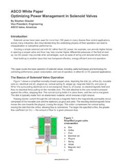
4 AS-i Bus NetworkAS-i is so simple and so inexpensive that it makes using traditional wiring methods difficult to I/O SYSTEMAS-i BUS NETWORKAS-i is inexpensive, simple, suppliesplenty of power and offers end usersa variety of wiring Comments on AS-iStrengthsAS-i is inexpensive,especially in general purpose is other communication protocols, AS-i is notdesigned to bring control system functionality to the field. AS-i is simplya better way to connect field devices to the control system. AS-i offersend users a variety of topologies (wiring strategies). And AS-i s principleof operation makes it easy to install and configure as well as add newdevices supplies plenty of delivers plenty of power to oper-ate virtually all field devices, including solenoid lengthThe maximum length of cable run is limited to 100 m per to two repeaters can be added to increase this length to 300 AreasSince AS-i is an 8 amp bus, it cannot be intrinsically safe.
5 TopWorx hasrecognized the difficulties of installing AS-i in hazardous areas andoffers a variety of solutions suitable for use in Class I, Div 1 (Zone 1)and Class I, Div 2 (Zone 2) to Use AS-iGenerally speaking, TopWorx recommends AS-i when:- device populations are all discrete- plants are not intrinsically safe- cable length limitations are not an issue- users desire the ultimate in simplicity- existing discrete devices need to be incorporated into a bussed environment- conventional discrete devices need to be incorporated into a bus network- large numbers of discrete devices need to be cost-effectively incorporated into an existing control level network via a gateway deviceSensor Bus NetworkTechnology DeveloperAS-i ConsortiumYear Introduced1993 OpennessMultiple vendors800+ products.
6 150 VendorsType of NetworkSensor BusPhysical Media2-wire cable (flat or round)Network TopologyBus, Ring, Tree, StarMaximum Devices- 31 nodes (or 248 I/O points)- nodes (or 434 I/O points)Maximum Distance- Maximum Distance100 meters - Maximum Distance with repeaters 300 meters(max. of 2 repeaters can be used)Communication Methods- Master/Slave with cyclic polling- Manchester Bit Encoding implemented via Alternating Pulse Modulation (APM)Transmission Properties- 5 mSec latency max. on fully loaded segmentPrimary usage - Signals- Signals (supports 12 bit analogsignals accessed over 5 cycles)Power and Communications on same twisted pair- Limited to 200mA per device power consumption- Requires AS-i specific power supply on communications bus for de-couplingDevice Power Supply- Devices can be supplied from bus (<200mA)- Additional power can be supplied by AS-i power bus cable having multiple power supplies (required for higher power outputs)Wiring TypesRound:Normal 2 wire cable#16 AWG ( )Flat.
7 2 wire flat AS-i cable ( conductors)Yellow for communicationsBlack for additional power Grounding aspectsUngrounded communications busShieldingUnshielded wireTerminatorsNo terminators requiredHazardous Area InstallationsExplosion Proof wiring requiredDevice Addressing- Automatic when connected one at a time to the segment or with Handheld Addressing UnitGoverning BodyATO (AS-i Trade Organization)Web