Transcription of Optimizing Power Management in Solenoid Valves
1 ASCO White PaperOptimizing Power Management in Solenoid ValvesBy Stephen GlaudelVice President, EngineeringASCO Valve, AmericasIntroductionSolenoid Valves have been used for more than 100 years in many diverse flow control applications,across many industries. But misunderstanding the underlying physics of their operation can lead to misapplication or suboptimal a simple Solenoid coil with AC rather than DC Power , for example, can provide higher forcesin opening a poppet valve and thus may help counter higher differential pressures of the fluid at startup, but DC Power may provide other advantages, such as ease of wiring and reduced shock hazard. Heat build-up is another issue that has hampered effective, energy-efficient Solenoid operation. This paper covers the basic operation of Solenoid Valves , including useful techniques and technology for Optimizing performance, Power consumption, and cost of operation, in either AC or DC powered Basics of Solenoid Valve OperationFigure 1 shows a simplified normally-closed poppet valve, depicting the disk (a), orifice (b), movablecore (c), electrical coil (d), plugnut (e), conical spring (f), airgap (g), magnetic field (h), and yoke (j).
2 When the surrounding electrical coil is not energized, there is, of course, no electromagnetic field andthus no electrical force pulling on the movable core. The disk attached to the core remains pressedagainst the orifice, stopping flow. The conical spring holds it in place there, until the coil is disk is typically made from an elastomeric material, which ensures a tight electric current through the coil induces a magnetic field in the magnetically permeable circuit,comprised of the movable core and the stationary plugnut and yoke. The resulting electromagnetic forcemoves the core towards the plugnut, closing the airgap. This action compresses the conical spring, moving the disk from the orifice, allowing flow to commence. The larger the specified orifice, the greaterflow coefficient (or Cv) the amount of flow for a given pressure closer lookThe simplified explanation above works equally well for AC or DC excitation, subtleties of internal construction notwithstanding.
3 But analysis of performance at various stages of operation reveals differences that can be exploited to gain performance improvement and energy the valve is just starting to open, force from the spring helps keep the orifice covered, but thisis augmented by hydraulic force produced by the pressure drop between the valve inlet and outlet. Thishydraulic force is proportional to the square of orifice size, since the area of pressure imbalance isequal to pi times the orifice radius squared. This is why opening Valves with greater flow often requiresa disproportionately larger coil and lifting force. However, once the valve is open and flow commences, the hydraulic force decreases an ideal Solenoid valve should have just enough initial electromagnetic lifting force to counter boththe spring tension and the hydraulic forces. But once flow starts and hydraulic force has diminished, the valve needs to consume only enough energy to compress the spring.
4 Providing the same amount of energy required to counter the initial hydraulic force simply creates waste or DCTo manage Solenoid Power consumption across various states of operation, AC excitation is usuallymore efficient than DC. Typically, an end user will supply AC voltage to the coil by activating a mechanicalor solid-state switch, for example. But the magnetic field is generated not by the voltage but by the currentpassing though the coil, multiplied by the number of coil turns. This current is equal to the voltage dividedby the coil an AC sine wave impedance is calculated as R + j*2*pi*f*L, where R is the coil resistance, L is its inductance, f is the AC frequency, and j is a mathematical operator that results in a 90-degreephase shift. As the Solenoid valve opens, the air gap quickly narrows. The core accelerates as themagnetic circuit becomes more efficient, increasing the coil s inductance, and thus the impedance,dramatically.
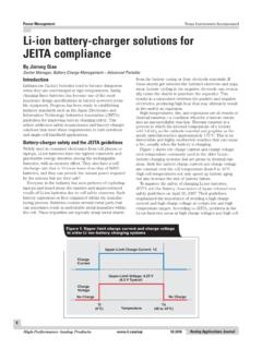
5 The increased impedance resulting from this initial inrush decreases the current. Thisgives the Power needed to counter enough pressure to open the valve, and then actually reducepower demand once a steady state is reached, following the curve depicted in Figure 2. With DC excitation, however, the case is reversed. Applying DC voltage to a Solenoid coil actually increases the current asymptotically (Figure 3) until it is equal to voltage divided by the coil time it takes to get to that steady-state level depends on the time constant of coil inductance dividedby resistance (L divided by R). Thus DC excitation, with its relatively slow buildup of current, creates exactly the opposite of the quick spike necessary for energy efficient the TradeoffsAlthough AC excitation is typically more efficient, it is not necessarily the best choice. AC usuallycomes with high voltages (120/240 V AC), which raises user issues such as wire segregation andshock hazards.
6 Low-voltage AC is of course available, but requires a transformer, which introducespower/heat issues. AC excitation is also subject to intrinsic losses. Since the voltage/current is cycling, in an AC solenoidsubstantial iron losses (hysteresis and eddy currents) can account for half of its Power is also not as suitable to many modern industrial applications that use programmable logic controllers (PLCs), distributed control systems (DCSs), and other digital technologies that automatefluid control and provide easier connectivity to DC loads. DC Power leverages its capability to offermore outputs per plug-in module or enable the user to share one output module between different loadtypes. And DC Power busses are often more readily available ( , 24 V DC with auctioneered backupsin many process plants).Making DC workThe ideal solution would be to achieve the current waveform shape of AC Solenoid excitation withoutall the inherent limitations.
7 To accomplish this, some Solenoid valve packages deploy additional electroniccomponents to bring the shape of the DC coil current waveform closer to AC curve. Figure 4 depicts asimple example of the operation of these additional spike and hold the coil is first energized with direct current, it spikes through and charges a capacitor (C). It then encounters the added resistor (R), which limits its continued flow through the coil, therebyminimizing subsequent energy consumption. But using an additional resistor, or any similar heat-generating component, in this way also adds heat to the system, confining this approach to smaller-sized Solenoid it is the larger solenoids in which Power conservation has the greatest payback. What s neededis a way to generate a high-current initial pulse from a DC voltage rail, and then reduce it quickly to theminimum Power level needed to keep the Solenoid valve open, and do so without dropping the steady-state current through a resistor, linear-mode transistor, or other technology that consumes more powerthan it to a New DesignASCO Valve has accomplished this through the development of an integral switching Power supplythat accepts a wide range of both AC or DC input.
8 Its circuits can be programmed to supply increasedcurrent to the coil during initial excitation and then drop back to maintenance in ASCO s RedHat Next Generation valve line, this technology delivers much improvedfluid performance, with higher flow rates and pressures, at a fraction of the steady-state electricalpowerconsumption of conventional designs. It also minimizes problems related to heat buildup in Solenoid the HeatAlong with the high operating costs associated with excess Power production are the performance andmaintenance complications from the heat itself. A bank of ten conventional 11-watt solenoids in a sealedcabinet, for example, can quickly raise internal temperatures beyond the specifications of other electronicsin the cabinet. Removing that heat from instrumentation systems can require fans, air-conditioning, or othercooling Solenoid coil heat also reduces a valve s life expectancy.
9 Differing grades of magnet-wire/insulationdo allow for larger or smaller tolerances for ambient system temperatures and for the increased temperaturecaused by a valve s own heat of operation, but eliminating the production of unnecessary heat in the firstplace makes more sense from both an operational and an economic is even a ten degree C rule of thumb, which suggests that a coil s thermal life approximatelydoubles for every ten degree Celsius reduction in operating temperature, all other things being is based on Arrhenius theory applied to a typical activation energy. If the current switching systemmentioned above can reduce the output of conventional 11-watt Solenoid coil by 2 watts, it would reducecoil temperature by about 40 degrees C, resulting in a lifetime increase of 2^(40/10), or 16, meaning thatyou could extend the service life of a Solenoid coil from 5 years to 80 unnecessary Power consumption in Solenoid coils saves money, improves valve performance,and extends valve operating life.
10 New digital designs overcome the energy consumption limitations of conventional AC and DC powered systems with a switching Power supply that enables users to deploy either AC or DC current for their applications, in a way that provides the initial Power spike necessary toopen the valve, while reducing Power demand to low levels needed to maintain steady state benefits are lower energy costs, lower failure rates, reduced maintenance costs, and dramatic life extension of the Valves . ABOUT THE AUTHOR Stephen Glaudel has been with Emerson Electric Corp. for 10 years, as a VP of Engineering for theASCO Valve and Brooks-Instrument divisions. Prior to Emerson, he held positions at Leeds & Northrupand Westinghouse. He holds a in Electrical-Engineering & Biosystems from Syracuse University,and an MBA from St. Joseph s