Transcription of SHAKING TABLE TESTING OF CIVIL ENGINEERING …
1 21291 National Laboratory For CIVIL ENGINEERING , Av. Brasil 101 - 1700-066 Lisboa Portugal , Laboratory For CIVIL ENGINEERING , Av. Brasil 101 - 1700-066 Lisboa Portugal , TABLE TESTING OF CIVIL ENGINEERING STRUCTURES - THELNEC 3D SIMULATOR EXPERIENCER ogerio BAIRRAO1 And Carlos T VAZ2 SUMMARYS haking tables are nowadays a valuable tool for the seismic behaviour assessment of civilengineering structures. The main purpose of this paper is to present some aspects of the recentexperience obtained throughout the accomplishment of several series of tests (on different types ofstructures) which were achieved using the new LNEC 3D earthquake simulator.
2 It should bementioned that the tests results are not presented, as the emphasis is focussed on the main issuesfound in order to perform the tests as close as possible both to the nature occurrences and thestructural behaviour. Some of the adopted solutions and procedures are described and eventualalternatives are the problems involved, the following are briefly highlighted:-Physical scales (dimensional analysis and similitude theories) to be adopted in thespecimens design;Instrumentation, respecting the type of transducers and the option between relative or absolutemeasurements;-Signal acquisition, in regard to the kind of sampling and filtering to adopt.
3 -Test strategies, defining the successive stage analysis, concerning the definition of the most profitable inputs, as well as controlalgorithms, related to the input signal reproduction and real time compliance with the dynamiccharacteristics modifications, are discussed in a separate paper (Duque and Bairrao, 2000).Moreover, handling and solving the above referred problems produced a valuable enhancedknowledge in what concerns the design and construction of auxiliary structures required by typicalset-ups involving the dynamic behaviour of models associated to large moving masses or inertiaforces and also concerning all the connection systems.
4 Mainly about the maximum allowable gapsand the required range of stiffness use of SHAKING tables for the assessment of the dynamic and seismic behaviour of CIVIL engineeringstructures is effective since the sixties. At the beginning, SHAKING tables had important limitations concerning thepower available and they have been used to study the dynamic characteristics (natural frequencies and modeshapes) of small models behaving essentially in the linear range. Meanwhile, bigger and more powerful shakingtables have been put in operation allowing for the adoption of lower scaling factors and therefore involving veryimportant dynamic a significant amount of research using SHAKING tables can be found in the literature.
5 This research hasbeen oriented mainly for the ultimate behaviour of steel and rc building structures, structural elements (with aclear emphasis on rc and masonry walls, rc frames with infills and dissipating devices) and global models ofstructures at smaller scales. Among the most paradigmatic examples of the use of SHAKING tables are the two21292series of tests performed at the Tsukuba facility on 1:1 scaled models; the first one was performed in theframework of the US-Japan Cooperative Earthquake Research Program on a building model with 7 storeys; morerecently (Minowa et al, 1996) two 3-storey building models have also been tested to failure.
6 In what concernsshaking TABLE tests on bridge structures and bridge piers, information is rather scarce and just a few results arefound in literature. The tests performed at LNEC (Carvalho et al, 1978), at the University of California(Williams and Godden, 1976) and at ISMES facilities (Casirati et al, 1996) are among the few papers publishedon the subject. Those tests have been performed on models at 1:100 scale (LNEC), 1:30 (UC) and 1:8 (ISMES).In order to advance its experimental activity in ENGINEERING , which started in the late fifties, LNEC decided tostudy and build a new type of earthquake simulator mainly conceived for the TESTING of CIVIL engineeringstructures, such as buildings and bridges, being, however, also useful for the validation of the dynamic behaviourof some mechanical and electrical very particular simulator has three independent translational degrees of freedom which are driven byhydraulic actuators.
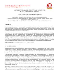
7 Whereas its rotational degrees of freedom are minimised by torque tube systems, one foreach axis (roll, pitch and yaw). Under the horizontal cranks, either passive gas actuators, to cope with the deadweights of the SHAKING TABLE and of the TESTING specimen, or rigid blocks, eliminating the vertical motion of thetable, can be inserted (Figure 1).At each end, the torque tubes are linked, by means of a crank, with a stiff connecting rod between them and themoving platform. The vertical connecting rods are pinned at both ends, and horizontal motion of the platform isallowed.
8 When the platform moves vertically, it either pulls or pushes the connecting rods, rotating both cranksby the same angular displacement, and the respective torque tube likewise. In fact, if there is an overturningmoment inducing a rotation on the platform, then vertical movement in opposed directions appears at the upperend of the connecting rods, which, in turn, causes small opposite rotating forces in the cranks. However, this isresisted through a large reaction force generated by torsional stiffness of the concerned very stiff torque tube,resulting only in an insignificant platform main characteristics of this SHAKING TABLE are an area of m x m, a TABLE mass of about 40 t, amaximum allowable specimen weight of 400 kN, a frequency range from 0 to 15 Hz, maximum accelerations , and g for the transverse, vertical and longitudinal axis respectively, and maximum displacements of 175 mm for all the three axes.
9 Detailed information on the characteristics of the SHAKING TABLE can be found in(Emilio et al, 1989).Figure 121293 PHYSICAL SCALES AND SIMILITUDE LAWSIn structural problems involving scaled models 2 types of similitude are most commonly considered. One ofthem is the Cauchy similitude, based on the Cauchy number and expressed as CN = v2 / E, which shall be thesame in the prototype and in the model. This type of similitude is adequate for phenomena in which restitutionforces are essentially elastic. The other type of similitude is the Froude similitude, adequate for situations inwhich gravity action plays a primary role.
10 In this case the Froude number, expressed as CF = v2 / (L g) shall besimilar in the prototype and in the model. In the previous expressions for the Cauchy and Froude numbers represents the specific mass, v the velocity, E the elasticity modulus, L the length and g the gravity TABLE I the Cauchy and Froude similitude relationships for the some quantities more usually considered instructural ENGINEERING are presented (symbol M refers to the model and symbol P to the prototype). TABLE I Similitude = LMLP = LMModulus of elasticityeEP = e EMEP = e EMSpecific mass P = M P = MAreaAAP = 2 AMAP = 2 AMVolumeVVP = 3 VMVP = 3 VMMassmmP = 3 mMmP = 3 mMVelocityvvP = e1/2 -1/2 vMvP = 1/2 vMAccelerationaaP = e -1 -1 aMaP = aMForceFFP = e 2 FMFP = 3 FMMomentMMP = e 3 MMMP = 4 MMStress P = e M P = MStrain P = M P = e-1 MTimettP = e-1/2 1/2 tMtP = 1/2 tMFrequencyffP = -1 e1/2 -1/2 fMfP = -1/2 fMConsidering the materials commonly used in the construction of structures.