Transcription of The Design and Construction of Concrete-Filled …
1 13th World Conference on Earthquake Engineering Vancouver, , Canada August 1-6, 2004 Paper No. 252 THE Design AND Construction OF Concrete-Filled steel TUBE COLUMN FRAMES by Stephen P. SCHNEIDER1, Donald R. KRAMER2 and Douglas L. SARKKINEN3 SUMMARY The Construction of a moment-resisting joint in a steel frame must accommodate the acceptable tolerances that occur during the production of structural shapes and during fabrication and erection. Further, the Construction should be economical; however, the joint must be of sufficient strength and stiffness to satisfy the intended structural integrity and seismic demands.
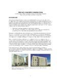
2 This paper describes the Design and Construction of a type of moment-resisting joint recently used for two low-rise buildings in Vancouver, Washington The joint consists of a structural steel wide-flange shape penetrating continuously through a composite Concrete-Filled steel tube (CFT). Examples of two joint types are considered: One in which the girder was attached to the column in the field, and the second consisting of shop fabrication of the critical joint. Each joint configuration was detailed to accommodate the needed tolerances of fabrication and field erection, while minimizing welded joints in critical regions of the connection.
3 The Design of frames with CFT columns is similar to frames using structural steel shapes for columns in which it is desirable to maintain a hinging girder joint. Thus, the ability to accurately compute the CFT column and joint strengths is imperative. Strength and stiffness estimates of the CFT column from both the American concrete Institute s ACI-318 and the American Institute of steel Construction 1994 AISC/LRFD provisions are compared. Each specification produces somewhat different values for strength, but the estimate of stiffness varies most significantly between the two provisions. Finally, one method to estimate joint strength, which is shown to depend significantly on joint configuration, is provided.
4 INTRODUCTION Concrete-Filled steel tube (CFT) columns combine the advantages of ductility, generally associated with steel structures, with the stiffness of a concrete structural system. The advantages of the Concrete-Filled steel tube column over other composite systems include: The steel tube provides formwork for the concrete , the concrete prolongs local buckling of the steel tube wall, the tube prohibits excessive concrete spalling, and composite columns add significant stiffness to a frame compared to more traditional steel frame Construction . While many advantages exist, the use of CFTs in building Construction has been 1 Kramer Gehlen & Associates, Inc.
5 , 400 Columbia Street, Suite 240, Vancouver, WA 98660-3413 2 Principal Emeritus, Kramer Gehlen & Associates, Inc. 3 Associate, Kramer Gehlen & Associates, Inc. limited, in part, to a lack of Construction experience, a lack of understanding of the Design provisions and the complexity of connection detailing. Consequently, a joint was needed that could utilize the favorable strength and stiffness characteristics of the Concrete-Filled tube column yet be constructible. This paper summarizes a steel girder to Concrete-Filled steel tube (CFT) connection detail that has been designed for several recent projects constructed in Vancouver, WA, Several variations of CFT joints have been investigated experimentally [1], and it appears that continuing the girder through the CFT column can induce full plastic hinging of the structural shape.
6 The practical connection has been designed to accommodate the needed tolerances resulting from the rolling process, fabrication and Construction . Circular CFTs were used because of their more favorable ductility characteristics relative to the square tube, and were more accommodating when the structural frames were not oriented along orthogonal axes. Two connection types will be discussed: One where the girder-to-column joint was produced in the field and the other in which the joint was shop fabricated. The Design of this connection is discussed, along with the relevant requirements from the applicable Design codes.
7 A Design methodology, which consists of the flexural strength, stiffness and equilibrium at the joint, is presented. Results suggest that the flexural strength of the CFT section depends on the assumptions used in the prediction of strength. However, stiffness controls the Design of many structural systems using moment-resisting connections. Flexural stiffness was shown to be highly variable, depending on the method of computation. Finally, a reasonable evaluation of joint equilibrium was needed to ensure proper inelastic behavior of the structural system. These issues are critical in obtaining a safe and economical CFT joint Design .
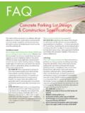
8 INELASTIC CONNECTION BEHAVIOR Figure 1 shows the results from two of the six circular CFT connections tested by Schneider, et. al. [1, 2]. In this study, only circular tubes were considered, since the connection of the girder to the tube wall tends to be more difficult when compared to the square tube counterpart. The Type I connection was a connection that was attached to the skin of the steel tube only. This connection was favored by many of the practitioners on the advisory panel for this research project since it appeared to be the easiest to construct. Effectively, the flanges and the web were welded to the skin of the tube, and the through-thickness shear of the tube wall controlled the distribution of flange force, or the flared geometry of the flange plate, to the tube wall.
9 The Type II connection had the girder section continue through the Concrete-Filled steel tube. An opening was cut in the steel tube to allow the girder to pass through the core. Each connection tested consisted of a 356 mm (14 inch) diameter pipe with a mm (1/4 inch) wall thickness and a W14x38 for the girder. The yield strength of the pipe and the girder was 320 MPa ( ksi), with an approximate concrete strength of 35 MPa ( ksi). In all cases in this test program the connection was intended to be shop fabricated. This was primarily to control the quality of all welded joints. A stub-out of the connection was intended to be attached to the tube column and shipped to the Construction site.
10 The field splice would be made to the end of the connection stub-out of the connection. As the Construction of the structural system progressed, the tube would be filled with concrete . Clearly, a connection like Type I provides the least amount of interference with the placement of the concrete infill. However, a connection like Type II may introduce significant difficulty in getting good consolidation of the concrete in the tube for lifts over several floors. As demonstrated by the normalized moment-rotation behavior shown in Figure 1, the connection that continued through the CFT exhibited far superior behavior relative to the exterior-only Type I connection.