Transcription of CONTROL JOINTS FOR CONCRETE MASONRY …
1 Provided An i n f o r m aby: tion series from the national authority on CONCRETE MASONRY technology Cemex, Inc. CONTROL JOINTS FOR. CONCRETE MASONRY WALLS TEK 10-2C. EMPIRICAL METHOD Movement CONTROL (2010). INTRODUCTION. CONCRETE MASONRY is a popular construction material MASONRY veneers differ from the guidance presented be- because its inherent attributes satisfy the diverse needs of low. The reader is referred to TEK 10-4, Crack CONTROL both exterior and interior walls. While these attributes for CONCRETE Brick and Other CONCRETE MASONRY Veneers are the primary basis for CONCRETE MASONRY 's popularity, (ref.)
2 3), for more detailed information. performance should not be taken for granted. Like all con- CONTROL JOINTS are one method used to relieve hori- struction systems, design decisions significantly influence zontal tensile stresses due to shrinkage of the CONCRETE field performance of the CONCRETE MASONRY wall system. MASONRY units, mortar, and when used, grout. They are Proper application of crack CONTROL measures, including essentially vertical planes of weakness built into the wall CONTROL JOINTS when required, can help ensure satisfactory to reduce restraint and permit longitudinal movement due performance of the CONCRETE MASONRY .
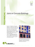
3 To anticipated shrinkage, and are located where stress con- Note that crack CONTROL considerations for CONCRETE centrations may occur. A bond break is accomplished by Between main and At maximum of intersecting wall one-half CONTROL joint spacing from corners At changes in wall height At pilasters and changes in wall Adjacent to lintel and through thickness opening if not crossing vertical reinforcement Figure 1 Typical CONTROL joint Locations Related TEK: Keywords: bond beams, construction details, CONTROL 7-1C, 10-1A, 10-3, JOINTS , crack CONTROL , joint reinforcement, reinforcing bars, reinforced CONCRETE MASONRY , shrinkage, wall movement 10-4.
4 NCMA TEK 10-2C 1. replacing all or part of a vertical mortar joint with a backer In addition, care should be taken to provide JOINTS at rod and sealant. This keeps the joint weather tight while locations of stress concentrations such as (see Figure 1): accommodating small movements. joint reinforcement and 1. at changes in wall height, other horizontal reinforcement should be discontinued at 2. at changes in wall thickness, such as at pipe and duct CONTROL JOINTS unless it is required for structural purposes, chases and pilasters, as it will act to restrain horizontal movement.
5 3. at (above) movement JOINTS in foundations and When CONTROL JOINTS are required, CONCRETE MASONRY floors, only requires vertical CONTROL JOINTS . When materials with 4. at (above and below) movement JOINTS in roofs and different movement properties, such as CONCRETE MASONRY floors that bear on a wall, and clay MASONRY , are used in the same wythe the move- 5. near one or both sides of door and window openings, ment difference needs to be accounted for in the design. (see following subsection, CONTROL JOINTS at Openings), Normally, joint reinforcement is used in the common and joint between the two to distribute the forces and keep 6.
6 Adjacent to corners of walls or intersections within a any cracks that form tightly closed. Another option is to distance equal to half the CONTROL joint spacing. provide a horizontal slip plane between the two materials Consideration must also be given to the effect of to accommodate the differential movement. See Clay and CONTROL joint placement on load distribution within the CONCRETE MASONRY Banding Details, TEK 5-2A (ref. 1), wall. For example, locating CONTROL JOINTS at the ends of for more detailed information. lintels may compromise arching action.
7 Therefore, it may CONTROL JOINTS are typically required in exposed above be prudent to design the lintel to carry the full weight of grade CONCRETE MASONRY walls, where shrinkage cracking the wall above it in addition to any superimposed loads. may detract from the appearance of the wall, and to limit moisture or air infiltration. Shrinkage cracks in CONCRETE CONTROL JOINTS at Openings MASONRY are not a structural concern. In addition, walls Because cracking occurs in the planes of greatest with adequate horizontal reinforcement may not require weakness, openings are particularly vulnerable.
8 For CONTROL JOINTS , as the reinforcement effectively reduces the an opening of up to 6 ft ( m) in width that are not width of shrinkage cracks. See TEK 10-3, CONTROL JOINTS wrapped with reinforcement, a CONTROL joint should be for CONCRETE MASONRY Walls Alternative Engineered placed at one side of the opening as shown in Figure 2a. Method (ref. 2), for more information. Notice that the joint goes around the lintel and allowance Foundation walls traditionally do not include con- for movement (a slip plane in the form of flashing or trol JOINTS due to concerns with waterproofing the joint other bond breaker) between the lintel and the MASONRY to withstand hydrostatic pressure.
9 Additionally, since must be provided. Because the lintel is not laterally sup- foundation walls are subjected to relatively constant ported at the bottom due to the slip plane, CONTROL JOINTS temperature and moisture conditions, shrinkage cracking capable of providing load transfer between panels are in below grade walls tends to be less significant than in required, such as the JOINTS shown in Figures 3a, 3d, 3e, above grade walls. 3f, 3h and 3i. This TEK focuses on cracking resulting from inter- In Figure 2a, continuous vertical reinforcement can- nal volume change of the CONCRETE MASONRY .
10 Potential not be provided in the cell adjacent to the opening on cracking resulting from externally applied design loads the left, as crossing the horizontal portion of the CONTROL due to wind, soil pressure, seismic forces, or differential joint ( , the slip plane) would effectively pin the two settlement of foundations is controlled by structural design sections together, restraining relative movement. To resist considerations not addressed here. Where external loads the lateral movement around the slip plane, 24-in. (610- are an issue in combination with internal volume change, mm) long horizontal joint reinforcement may be placed the design should consider the combined effects of these at the lintel bearing location and two courses below.