Transcription of Section 6 General Development of Multiplexing - …
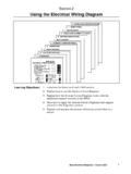
1 Section 6. General Development of Multiplexing Learning Objectives: 1. To review the Development of automotive Multiplexing . 2. To discuss the application of Multiplexing systems. 3. To correctly use the Hand held tester to retrieve codes and access Freeze Frame Data. 4. To effectively use the Active Test Mode using the Hand held tester. body electrical Diagnosis - Course L652 1. Section 6. 2 LEXUS Technical Training General Development of Multiplexing Multiplexing In vehicle networking involving time division is also known as Multiplexing . It is a method for transferring data among distributed electronic modules via a serial data bus. Serial data is electronically coded information which is transmitted by one computer and received and displayed by another computer. The term serial data implies that the information is digitally coded and transmitted in a series of data words. Serial data gets its name from the fact that data parameters are transmitted, one after another, in series.
2 The display on the receiving computer updates or refreshes once each data cycle, after all data has been received. Transmission of Using an analog/digital circuit, the transmitting computer digitizes the Data and Rates data from sensors, actuators, and other calculated information. Typically, this means that each sensor or actuator value is converted into a one byte (8 bits) binary word before it is transmitted to the receiving computer. The data transmission rate is referred to as the baud rate. Baud rate refers to the number of data bits that can be transmitted per second. For example, if a data stream has 12. parameters, and each parameter is converted into an 8 bit data word, the total size of the data transmission is 96 bits of data (12 words x 8. bits per word.) If this data can be transmitted once every second, the baud rate is 96 bits/second or 96 baud. Without serial networking, inter module communication requires dedicated, point to point wiring resulting in bulky, expensive, complex, and difficult to install wiring harnesses.
3 Applying a serial data bus reduces the number of wires by combining the signals on a single wire through time division Multiplexing . Information is sent to individual control modules that control each function, such as anti lock braking, turn signals, power windows, dashboard displays, and audio systems. Advances and In vehicle networking provides system level benefits, many of which Standards are only beginning to be realized: A decreased number of dedicated wires is required for each function, and thus reduces the size of the wiring harness. System cost, weight, reliability, serviceability, and installation are improved. Common sensor data, such as vehicle speed, engine temperature, etc. are available on the network, so data can be shared, thus eliminating the need for redundant sensors. body electrical Diagnosis - Course L652 3. Section 6. Networking allows greater vehicle content flexibility because functions can be added through software changes. Existing systems require an additional module or additional I/O pins for each function added.
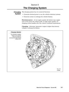
4 Car manufacturers are discovering new features that are enabled by networking. For example, Multiplexing allows driver's preference for such things as ride firmness, seat positions, steering assist effort, mirror positions, and radio station presets. Recently, there have been efforts to standardize protocols at the data link and physical layers. Systems designers are also seeing the benefits of standardized application layer protocols. Multiplexing Standards are also appearing in automotive applications. Examples include: SAE. J1939, OSEK from the German automotive consortium, SDS from Honeywell, and DeviceNet from Allen Bradley. These standards allow system designers to avoid low level protocol details and focus on the application itself. However, the impact of this type of standardization is increased demand on the microcontrollers and protocol devices; and thus the need for efficient message handling and standardized protocol. Typical Multiplexing System 4 LEXUS Technical Training General Development of Multiplexing Early Designs The early days of networking involved proprietary serial buses using generic UART (Universal Asynchronous Receiver/Transmitter) or custom devices.
5 This type of networking was acceptable in the United States because the Big Three (Ford, GM, Chrysler) were vertically integrated and were not highly dependent on external suppliers. However, in Europe and increasingly now in the , car manufacturers utilize many external suppliers. Proprietary protocols pose many difficulties with suppliers who need many special system designs to conform to the different protocols. Standard protocols allow modules from many suppliers to easily link together forming a type of open architecture." An open architecture will allow standardized diagnostic and emissions testers and will allow suppliers to benefit from economies of scale of mass produced standard protocol devices. These facts help to explain why diagnostics and systems designs were not widely published in many repair manuals or other forms of literature published by automotive manufacturers. Since the advent of standards the information regarding these Multiplexing systems has become increasingly more accessible.
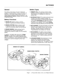
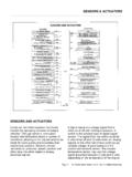
6 SAE Class A. Classifications/. Speeds Low Speed (<10 kbps [kilobits/second]). Convenience features (entertainment, audio, trip computer, etc.). Class B. Medium Speed (10 kbps to 125 kbps). General information transfer (instrument cluster, vehicle speed, emissions data, etc.). Class C. High Speed (125 kbps to 1 Mbps [Megabits per second] or greater). Real time control (powertrain control, vehicle dynamics, brake by wire). body electrical Diagnosis - Course L652 5. Section 6. Wiring Diagram for a Typical Class B Multiplex System Lexus systems such as the one pictured here it is possible to view the signal transmissions to and from the control unit along the data links with an oscilloscope. Assuming that the scope is set at the appropriate capture rate the signal pattern will be displayed. Unfortunately, without signal printouts and engineering specifications these scope patterns cannot be fully analyzed. This type of diagnosis does tell the technician that communication is occurring.
7 What it does not reveal is the nature of the communication or its accuracy. Nevertheless, it can be valuable when tracing the presence of a signal along a specific pathway connector to connector. The first line of diagnostics when dealing with Lexus Multiplexing must be the verification, the Repair Manual, and the Diagnostic Tester. Anything less is simply guess work. Diagnostic Trouble Codes include SAE controlled codes and manufacturer controlled codes. SAE controlled codes must be set as prescribed by the SAE, while manufacturer controlled codes can be set freely by the manufacturer within the prescribed limits. There is also a check mode for technicians to simulate malfunction symptoms and to troubleshoot. Basically, the body ECU monitors the communication within the network and triggers a code when there is an interruption in communication, a +B short, or a GND short. 6 LEXUS Technical Training General Development of Multiplexing Using The use of the Lexus Diagnostic Tester for the diagnosis of the Lexus Multiplexing DTCs is explained in detail in the Repair Manual.
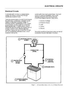
8 As Diagnostic these systems evolve, changes occur from model year to model year. In Tester order to avoid unnecessary repairs and loss of valuable shop time, it is very important that the technician read and understand the repair manual instructions for a particular model and year. Example: In the 1998 LX 470 Repair Manual it is noted during the Pre Check instructions that unless the body ECU is functioning normally there is the possibility" the diagnosis for other units will not be accurate. Also, there are conditions under which an accurate DTC will not be given even though the body ECU is normal. Next, there is a procedure for checking the body ECU/CPU in order to determine whether or not it is working properly. It involves confirming the operation of the body ECU and the Open Door Indicator. This procedure falls under the heading of Basic Inspection". The important thing to keep in mind is that unless you can be sure that the ECU. responsible for diagnostics is functioning properly, all other information may not be of value.
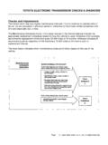
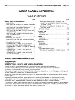
9 There are also certain malfunction configurations where a DTC will not be detected. Pre-Check body electrical Diagnosis - Course L652 7. Section 6. Circuit There are several layers of operation to consider when troubleshooting Operation a Lexus Multiplexing system. Let's take a look at the construction of a system. Keep in mind that these systems are very sensitive to electronic variables within the environment. Furthermore, we have mechanical operation of various components and these too can cause problems for the system. Take a look at a typical Tilt/Telescopic Switch. In this case it comes from an LX 470. Now that the ECU has the signal from the switch it executes a command to the Telescopic motor. In this example, the command is Contract". Remember, all positions of components (motors, switches). are known to the Instrument ECU. This memory function is one of the wonders of Multiplexing ; but it is also one of the potential problems. Why? Because all signals, confirmations, positions, ON/OFF settings must travel through the communication lines in order to make adjustments.
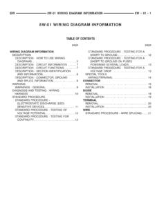
10 If there are any breakdowns along these lines then the system will not function properly. Also, bear in mind that any out of range" transmissions can be misinterpreted and the result will be a DTC, a malfunction, or an inoperative condition. Look at the following diagram as the ECU interacts with the motor in the Telescopic circuit. Keep in mind that the procedures for diagnosing these systems may vary from year to year and from model to model. Once again, the diagnosis of any multiplex system should not be attempted without the Repair Manual in hand. 8 LEXUS Technical Training General Development of Multiplexing Circuit Operation Control and DTCs body electrical Diagnosis - Course L652 9. Section 6. Multiplexing Communication Bus 1998 LX 470 EWD p. 136. 10 LEXUS Technical Training General Development of Multiplexing Using the Although the theory of Multiplexing is important to diagnostics, it is Diagnostic just as important to understand the use of the hardware and software Tester designed to assist in the diagnosis of the various systems.