Transcription of Types S100K and S102K Pressure Regulators
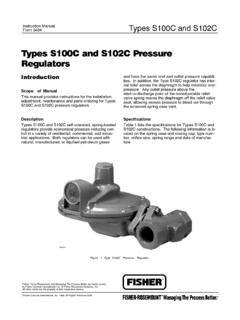
1 01/01 Types S100K and S102 KInstruction ManualForm S100K and S102K Pressure RegulatorsFigure 1. Types S100K and S102K Pressure RegulatorIntroductionScope of ManualThis manual provides instructions for the installation,adjustment, maintenance, and parts ordering forTypes S100K and S102K Pressure S100K and S102K direct-operated, spring-loaded Regulators provide economical pressurereducing control in a variety of residential, commercial,and industrial applications. Both Regulators can beused with natural, manufactured, or liquified petroleumW7478-1gases and have the same inlet and outlet pressurecapabilities.
2 In addition, the Type S102K regulator hasinternal relief across the diaphragm to help minimizeoverpressure. Any outlet Pressure above the start-to-discharge point of the nonadjustable relief valve springmoves the diaphragm off the relief valve seat, allowingexcess Pressure to bleed out through the screenedspring case for Types S100K and S102K construc-tions are given on page 2. The following information islocated on the spring case or closing cap: typenumber, orifice size, spring range, and date of S100K and S102K2 SpecificationsBody Sizes and End Connection Styles(1)3/4 x 3/4 (20 x 20), 3/4 x 1 (20 x 25),1 x 1 (25 x 25), 1 x 1-1/4 (25 x 32),1 x 1-1/2 (25 x 40), 1-1/4 x 1-1/4 (32 x 32), or1-1/2 x 1-1/2-inches (DN 40 x 40) NPT screwedOrifice Sizes, Inches (mm)1/8 (3,2), 3/16 (4,8), 1/4 (6,4), 5/16 (7,9),3/8 (9,5), 1/2 (12,7), 3/16 x 1/8 (4,8 x 3,2), or9/16 x 5/8 (14,3 x 15,9)Maximum Allowable Inlet Pressures(2)See table 1 Outlet Pressure Range(2)
3 See table 2 Maximum Emergency Outlet Pressure (Casing)(2)25 psig (1,7 bar)Maximum Operating Pressure to Avoid InternalPart Damage(2)3 psi (0,21 bar differential) above outlet pressuresettingTemperature Capabilities(2)-20 to 160 F (-29 to 71 C) Pressure RegistrationInternalApproximate pounds (2,04 kg)InstallationPersonal injury, equipment damage, orleakage due to escaping gas or burstingof Pressure -containing parts might resultif these Regulators are overpressured orinstalled where service conditions couldexceed the limits for which the regulatorswere designed, or where conditionsexceed any ratings of the adjacent pipingor piping connections.
4 To avoid suchinjury or damage, provide Pressure -relieving or Pressure -limiting devices (asrequired by the appropriate code, regula-tion or standard) to prevent serviceconditions from exceeding those , physical damage to a regu-lator could cause personal injury andproperty damage due to escaping gas. Toavoid such injury and damage, install theregulator in a safe regulator may vent some gas to theatmosphere in hazardous or flammablegas service, vented gas might accumu-late and cause personal injury, death orproperty damage due to fire or a regulator in hazardous gas serviceto a remote, safe location away from airintakes or any hazardous location.
5 Thevent line must be protected againstcondensation or installing the regulator, check for damage whichmight have occurred in shipment. Also check for dirt orforeign matter which may have accumulated in theregulator body or in the pipeline. Apply pipe compoundto the male threads of the pipeline and install theregulator so that the flow is in the direction of the arrowcast on the side of the body. The diaphragm casingassembly can be rotated to any position relative to thebody, in 90 increments. Remove the two cap screws(key 18, not shown) that hold the body to the actuatorin order to rotate the diaphragm casing not install the regulator in a location where therecan be excessive water accumulation, such as directlybeneath a downspout or in an undrained obtain the maximum flow capacities or other perfor-mance characteristics, the length of pipe from the reg-ulator outlet to the meter or for the first 18 inches(457 mm)
6 , whichever is closer should have no bendsand should be the same size as the regulator the regulator if water gets into the springcase or the lower casing of the S100K and S102K Regulators have a springcase vent (1-inch NPT female is standard; optional3/4-inch NPT female) which is screened to preventinsects or foreign material from End connections for other than standards can usually be provided, consult the Fisher Sales Office or Sales The Pressure /temperature limits in this instruction manual and any applicable standard or code limitation should not be S100K and S102K3 You are advised to use new vent pipingbecause defective threads on the reliefvent piping may interfere with the ventingassembly if the piping obstructs themovement of the vent indoor installations.
7 The vent should be piped out-side the building, see figure 2. Remove the screenfrom the regulator vent connection and connect ventpiping from that connection to the outdoors. Vent pip-ing should be as large in diameter as practical, be asshort as possible, and have a minimum number ofbends and elbows. Install a weather and insect resis-tant vent assembly on the outside end of the pipe,such as a Fisher Type Y602. The same installationprecautions apply to vent assemblies as the integralregulator vents described program of regular inspection of the vent openingshould be established to see that it has not becomeplugged by foreign material.
8 On some installations,such as in areas of heavy snowfall, it may be neces-sary to install the regulator beneath a protective other protection is provided from the elements, thevent should be pointing or sloping down sufficiently toallow any condensate to drain. Also check the regula-tor periodically for external or internal ProtectionSome type of overpressure protection isneeded if actual inlet Pressure can exceedthe outlet Pressure rating. Overpressur-ing any portion of this equipment abovethe limits given in the Specifications andtables 1 and 2 may cause damage toregulator parts, leaks in the regulator, orpersonal injury due to bursting of pres-sure-containing parts or explosion ofaccumulated S102K Regulators provide internal relief that lim-its the total outlet Pressure buildup over setpoint.
9 Thisinternal relief may be adequate for the application, ifnot, provide additional Pressure relief or a Pressure -limiting device downstream. External downstreamoverpressure protection is required on Type S100 Kbecause this unit does not have an internal reliefvalve. Regulators should be inspected for damageafter any overpressure avoid personal injury or property dam-age due to explosion or damage to regu-lator or downstream components duringstartup, release downstream Pressure toprevent an overpressure condition on thediaphragm of the order to avoid an overpressure condi-tion and possible equipment damage.
10 Pressure gauges should always be usedto monitor pressures during Check to see that all appliances are turned Slowly open the upstream shutoff Slowly open the downstream shutoff valve4. Check all connections for Make final control spring adjustments according tothe adjustment Light the appliance increase the outlet Pressure setting of the regula-tor, the adjusting screw (key 3, figures 4 & 5) must beturned clockwise. This requires removal of the closingcap (key 4, figures 4 & 5). To reduce the outlet pres-sure setting, turn the adjusting screw counterclock-wise.