Transcription of AXIOM Knife Edge Perimeter Trim - Select Acoustic
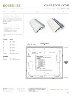
1 1 DescriptionAxiom Knife Edge is a Perimeter trim system designed for use with any of Armstrong s suspension systems. Field fabrication is limited to component assembly, straightcuts and minor adjustments to accommodate differencesbetween design dimensions and actual field versions of the product are available. AXKE2 STR isdesigned for use with acoustical lay-in or tegular panels anddrywall. AXKEV2 STR is for use with full panel installations ofthe Vector family of instructions are divided into five sections detailingmaterial delivery and identification, component assembly,AXKE2 STR Installation, AXKEV2 STR installation and finaldetailing.
2 Please carefully review all appropriate sectionsbefore proceeding with MATERIAL DELIVERY AND DeliveryAxiom Knife Edge components and hardware are delivered tothe job site in custom designed packaging. Exerciseappropriate care to protect the finished surfaces of thechannel ReviewReview the packing slip to insure that the complete order hasbeen delivered to the COMPONENT Splice Plates and Alignment ClipsSteel splice plates are used to align and secure all jointsbetween sections of AXIOM Knife Edge trim . Alignment clipsserve to position the outer edges of the trim sections.
3 Eachjoint will require one splice plate and one alignment plates are secured to the trim sections using factory-installed setscrews. Where desired, it may be beneficial tocaulk or tape the backside of the vertical joints to preventlight Position the splice plate (AX4 SPLICEB) so that it is roughly centered on the joint between Tighten the four setscrews to secure the splice to the trim . CAUTION: do not over tighten thesescrews to the point where they distort the face ofthe Install the Alignment Clip (AXKEALIGN) by insertingthe flat end into the groove located behind theleading edge of the trim .
4 Press the back end of theclip down to lock in Alignment PlateAX4 SPLICEB Splice PlateBetween us, ideas become reality CEILINGSYSTEMSAXIOM Knife Edge Perimeter TrimInstallation Corner AssemblyFactory assembled inside and outside corners come pre-mitered, bonded and finished. The legs of the cornermeasure 12" along the edge of the flange that supports the suspension system. Corner sections are installed using AX4 SPLICEB splice plates and Alignment clips(AXKEALIGN) at each T-Bar Connection Clips suspended ceilingsT-Bar Connection Clips are used to attach the AXIOM KnifeEdge trim to the supporting suspension system two-piece clips are supplied as an assembled unit withthe steel locking screw factory installed.
5 One clip is required ateach location where the grid system intersects the :For installation of T-Bar Connection Clips in drywallapplications refer to the Drywall trim Connection Clips are attached to the grid membersusing screws supplied by the installer. Framing screws (#6 x 7/16" or 1/2" lg.) are typical. Special conditions such as open cell installations may dictate the use of alternatemethods of attachment. See detail drawings, (page 3) for alignment of the connectionclip with the grid procedure - Suspended Ceiling Cut grid to Attach clip to grid Engage clip in channel bosses and tighten locking Drywall TrimDrywall trim is used to finish the edges of gypsum panels thatare applied to drywall grid finished with AXIOM Knife Edgetrim.
6 AXIOM drywall trim sections are factory formed to fit intothe groove inside AXIOM Knife drywall trim is set in place then fastened using standarddrywall screws applied through the tapping flange of the triminto the drywall suspension system. After installation the trim is finished using standard drywallmaterials and techniques. Normally, the drywall and AxiomKnife Edge is then painted to meet job T-Bar Connector Clip Installation DrywallIMPORTANT NOTE: Use only the AX-V-TBC T-Bar ConnectorClip for drywall Cut the clip off 1/16" above the score line forapplication of 1/2" drywall.
7 Cut 3/16" above thescore line (half way between the score line and thebottom of the screw slots) when using 5/8" Attach the modified AX-V-TBC clips to the drywallgrid system using two framing screws for each Install the AXIOM Knife Edge trim and tightenclamping Procedure - Drywall Install drywall suspension system and AXIOM KnifeEdge Attach drywall to the Install AXIOM Drywall Tape and finish Hold Down Clip for Metal Use the AXSPTHDC clip to hold the face of cutmetal panels down on the flange of the AXIOM One clip will be required for about every foot of cutpanel Insert the top of
8 The clip into the AXIOM trim first,then press up on the clip and engage the Hold Down ClipAX-V-TBC AXDWT in AXKE2 STR Knife Edge with Drywall Bottom TrimAXTBC T-Bar Connector ClipKNIFE EDGE AXIOMAXTBCAXTBCK nife Edge AXIOM4 GENERAL INSTALLATION Layout and install the suspension system accordingto the reflected ceiling Plan your grid layout to maximize the length ofcross tees that will support AXIOM Knife Edgecomponents. Suspend the system using minimum 12 gage steelwire spaced no more than four feet on center alongthe mains.
9 Additional wires may be required withineight inches of the cut ends of all grid componentsin areas where severe seismic activity is Brace and square the suspension Although not absolutely necessary, bracing willgreatly increase the speed and accuracy ofcompleting the remainder of the installation, and ishighly The grid system can be braced diagonally to thestructure above using either splayed wires, or rigidbracing members such as angles or cold rolledchannels. In either case, install bracing in the planeof both main beams, and cross Squaring can be accomplished by temporarilyclamping a rigid member (main beam or wall angle)diagonally across the topside of the grid system tomaintain 90 alignment of the mains and An alternate method is to cut scrap gridcomponents to fit diagonally into the ceilingmodule.
10 When installed in pairs, these short bracesare effective during layout and installation, and canbe reinstalled on top of the ceiling panels tomaintain alignment of the For small installations, it may be preferable toassemble, mark and cut the suspension systemcomponents on the floor, and then to suspend andbrace the grid Assemble and position the AXIOM components on topof the suspension Temporarily assemble the AXIOM componentsresting on top of the grid system. Check alignmentand clamp the components in Mark the location where the open side of the Axiomtrim rests on the grid members.