Transcription of Potential Leak Issues With 90 PSIG Nitrogen by William M ...
1 P O B o x 3 11 5 4 S t . L o u i s, M O 6 3 1 3 1 - 0 1 5 4 P h o n e : ( 3 1 4 ) 9 6 6 - 8 9 1 9 ~ E m a i l : w m h u I t t @ a o l . c o m 1 Potential Leak Issues With 90 PSIG Nitrogen by William M. Huitt (From a letter dated March 5, 2001 in response to a leaking Nitrogen line) If there is a Potential leak in the Nitrogen line we discussed on 3/2/01 I would check the flange joints in the stainless steel section of the system. The stainless steel spec. calls for a flange joint consisting of a stub-end and a lap joint backup flange. It indicates the use of a Type A stub-end under the heading of "Joints" without providing any further detail in the specification. This kind of ambiguity could be a source for accidental, or intentional, deviation from the intended type of joint. The wrong type of stub-end in combination with a 1/16" Teflon gasket minimizes, to a large degree, the sealing integrity of that joint.
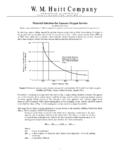
2 You can see by Detail 1 the different types of stub-ends that are available. Types A & B are manufactured and type C is flared pipe or tubing. The type C stub-end can either be purchased or it can be tubing flared by the fabricator. Looking at Detail 2 you can see how the Type A stub-end (also referred to as a Lap-Joint stub-end) has an outside knuckle radius that conforms to the radius of the lap-joint flange. Types B & C are squared off to conform more to a slip-on flange. The thickness of the flared portion of the types A & B stub-ends can be no less than the thickness of the pipe or tubing. However, the type C stub-end can be 75% the thickness of the pipe or tubing making it more susceptible to damage due to poor handling. In addition, the type C stub-end does not have serration's on the facing of the flare to provide sealing influence.
3 Detail 1 Detail 2 In resolving the Nitrogen leak problem I would flush the system thoroughly, isolate the suspected section of tubing then gradually apply an air pressure up to the operating pressure of 90 psig. A soap test can be performed on each of the joints during the gradual pressurization of the system. If a leak is located at a flange joint the following recommendation is made: 1. Disassemble the flange joint 2. Check for the following: a. Alignment are the two stub-end faces parallel to one another? b. Cold spring did the connection spring apart when unbolted? c. Type stub-end were type A sub-ends used? d. Facing is the face of the stub-end serrated? e. Gasket 1/16" or 1/8" gasket? f. Damage is there any damage or distortion to the face of the stub-end? Resolution to findings: 1.
4 Alignment & cold spring: 2 a. Modify tubing to allow the two stub-end faces, when properly supported, to align with one another without force. b. Check to see if the flange is bored out for tubing The spec calls for an ASME lap joint flange with tubing bore that doesn't exist. The backup flanges for tubing stub-ends are not per Code. Those types of flanges are basically a plate flange that is a proprietary to each manufacturer. I'm not sure what the fabricator/installer would have used. If it is a standard lap joint there will plenty of room for misalignment. 2. Type stub-end: a. The stub-end and the backup flange have to be compatible. If a Type A stub-end (per spec) is used and the backup flange has a square inside edge it will not distribute its load properly across the face of the stub-end.
5 Make sure the inside diameter of the flange is not bottoming out on radius of the stub-end. b. If the stub-end is a field flared Type C stub-end, remove and replace it with a Type A. 3. Stub-end facing: a. Make sure the sealing surface on the stub-end is serrated. 4. Gasket: a. Replace the gasket with an 1/8" thick Garlock Gylon #3540 Teflon gasket. This is a highly compressible gasket that will help compensate for a limited amount of surface damage and misalignment. 5. Damage: a. If the face of the stub-end is damaged or distorted in any way, remove and replace it. As a suggestion, when using stub-end connections, in either gaseous or liquid service, always use a highly compressible gasket with a 1/8" minimum thickness as mentioned in 4a above. These fittings can be mishandled and not always repaired properly or replaced, as they sometimes should be.
6 The added compressibility and thickness of the aforementioned gasket type helps to compensate for a flawed sealing surface on the stub-end. In case you do use the above mentioned gaskets, or something similar, and wish to verify the sealing quality of the installation I am including a table of torque values for that type of gasket. Bolt Torque Values for ASME 150# Class Raised Face Flanges With A193 Grade B7 Bolts For Garlock Gylon Gaskets and Other Compressed Sheet Gaskets Nom. Pipe Size (Inches) No. Of Bolts Size Of Bolts (Inches) Internal Pressure (PSIG) Minimum Torque ( ) Preferred Torque (ft. lbs.) 1/2 4 1/2 300 9 28 3/4 4 1/2 300 13 40 1 4 1/2 300 17 53 1 1/2 4 1/2 300 35 60 2 4 5/8 300 69 120 3 4 5/8 300 81 120 END OF LETTER