Transcription of Critical Service Bulletin - tcmlink.com
1 Box 90 Mobile, AL 251-436-8299 PAGE NOREVISION2008/03/142013/07/171 of 4 CSB08-3C 2013 Continental Motors, 2 CSB08-3 CSupersedes SB08-3 BTechnical PortionsFAA ApprovedCONTINENTAL MOTORS AIRCRAFT ENGINECRITICAL Service BULLETINCOMPLIANCE NECESSARY TO MAINTAIN SAFETYSUBJECT: Throttle and Mixture control LeversPURPOSE:Remove bronze control levers from serviceCOMPLIANCE: At next 100-hour or annual inspection, or the next time the control lever is removed for any reason, whichever occurs firstMODELSAFFECTED:All continuous flow fuel injection engines ( All IO-240, IO-360, LTSIO-360, TSIO-360, IO-346, IO-470, GIO-470, TSIO-470, IO-520, GTSIO-520, LIO-520, TSIO-520, IO-550, GIO-550, TSIO-550, and TSIOL-550 engines) except FADEC equipped engines and those engines utilizing control levers secured by a pin on the shaft -see item 3 FORREVISION: To address pinned levers not included in previous document INFORMATIONC ontinental Motors (CMI) is aware of occurrences in which the bronze control levers for the mixture or throttle were not torqued adequately by the installer and have become loose.
2 This could lead to a loss of engine control and/or loss of engine replaced the bronze throttle or mixture control levers with stainless steel equivalents in 2008. 1. Original control levers designed for threaded shafts were manufactured from a bronze material and featured a non-machined (smooth) female chamfer on one side, which mated to the machined splined male chamfer on the throttle and mixture control The replacement control levers are manufactured from stainless steel and feature a machined (splined) female chamfer, which interlocks with the machined splined male chamfer on the throttle and mixture control shafts (Refer to Figure 1 for control lever identification).3. In addition to the levers mentioned in the paragraphs above, certain installations utilize bronze levers that are secured to the shaft with a steel pin.
3 This Bulletin does not address those installations. Refer to the applicable periodic inspection intervals in the engine Maintenance and/or Overhaul is aware that some bronze control levers were improperly installed on threaded shafts in the field, and the mechanical interlock was absent. Therefore, as part of our ongoing quality interests: All bronze control levers on threaded shafts of Continental Motors fuel injection systems must be REMOVED and REPLACED with stainless steel control levers during the next 100-hour or annual inspection or at the time a throttle or mixture control lever is removed for any reason, whichever occurs first. Box 90 Mobile, AL 251-436-8299 PAGE NOREVISION2008/03/142013/07/172 of 4 CSB08-3 CFigure 1.
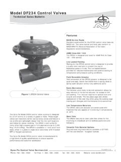
4 Throttle and control Lever IdentificationWARNINGTo Prevent the Possibility of Serious Bodily Injury or Death, Verify the following conditions prior to performing any Inspection, Repair or Movement of the Propeller:Aircraft Master Power and Magneto Fuel Selector Valve ..OFFT hrottle Position .. CLOSEDM ixture IDLE/CUTOFFSet Brakes and Place Wheel Chocks Forward and Aft of the Main Landing Gear Tires; Install Aircraft Tie-Downs and Verify Cabin Door Latch is OPEN. Do Not Stand or Place Equipment in the Arc of the Box 90 Mobile, AL 251-436-8299 PAGE NOREVISION2008/03/142013/07/173 of Inspect the component s shaft and the NEW stainless steel control lever to ensure no damaged or stripped threads exist and that the splines are well formed and without deformation or material loss (See Figure 2).
5 Figure 2. New Stainless Steel control Lever and Shaft2. Install the current style, stainless steel control lever onto the component shaft, positioning the lever to allow for proper airframe control interface (consult the Airframe Manufacturer s adjustment instructions).NOTE: The current stainless steel control levers are manufactured with machined splines that are intended to interlock with the splines on the mixture and throttle control shaft. Due to machining tolerances; the splines of a control lever and its mated shaft may not match (interlock) perfectly. However, testing has shown that control levers correctly installed and properly torqued will mate and function as intended, even if some mismatching of splines is Ensure that the splines in the control lever chamfer are meshed with the splines on the component shaft (see NOTE: above)4.
6 Lightly lubricate the control shaft threads with clean 50-weight engine Install and tighten a NEW retention lock nut on the shaft to secure the lever; rotate the lever away from the stop pin and torque the nut 100-120 inch-pounds. 6. Check the control lever after torque application to ensure there is no free play or movement of the control lever on the component If free play or movement is felt after the nut is torqued to the correct value, remove the control lever and determine the cause for movement (if applicable, re-install the control lever and repeat steps 3 through 6 above. If lever continues to have free play after being torqued, replace the control lever). Box 90 Mobile, AL 251-436-8299 PAGE NOREVISION2008/03/142013/07/174 of 4 CSB08-3 CIII.
7 Continued Airworthiness InstructionsAt each 100-Hour or Annual Inspection:WARNINGAny control lever or shaft exhibiting damage must be replaced prior to further Service using the procedures contained in the applicable Maintenance or Overhaul Manual and this Service Verify the stainless steel throttle and/or mixture control levers are securely installed on the control Inspect the installed lever(s) for looseness or free play on the shaft - looseness or free play of the lever on the shaft is prohibited. 3. Verify the retaining nut (if used) is torqued 100-120 3. control Lever and Shaft Spline Inspectio