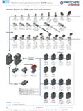
Transcription of Series M Miniature Rockers General Specifications
1 Series MMiniature PBSlidesProgrammableBRockersTouchTilt TogglesGeneral SpecificationsElectrical Capacity (Resistive Load) Power Level (silver): 6A @ 125V AC & 3A @ 250V AC 4A @ 30V DC for On-None-On; 3A @ 30V DC for all other circuits Logic Level (gold): maximum @ 28V AC/DC maximum (Applicable Range ~ @ 20mV ~ 28V) Logic/Power Level (gold over silver): Combines silver & gold ratings Note: Find additional explanation of dual rating & operating range in Supplement Ratings Contact Resistance: 10 milliohms maximum for silver; 20 milliohms maximum for gold Insulation Resistance: 1,000 megohms minimum @ 500V DC Dielectric Strength: 1,000V AC minimum between contacts for 1 minute minimum; 1,500V AC minimum between contacts and case for 1 minute minimum Mechanical Life: 50,000 operations minimum Electrical Life: 25,000 operations minimum for silver; 50,000 operations minimum for gold; 50,000 operations minimum for silver at 3A @ 125V AC Angle of Throw: 25 Materials & Finishes Actuator Clip & Mounting Frame: Stainless Steel Body Frame: Stainless steel Case: Diallyl phthalate resin (UL94V 0) Movable Contactor: Phosphor bronze with silver or gold plating Movable Contacts: Silver alloy (code W); copper with gold plating (code G); or silver alloy with gold plating (code A) Stationary Contacts: Silver with silver plating (code W); copper or brass with gold plating (code G); or silver with gold plating (code A) Terminals: Copper or brass with silver plating.
2 Or copper or brass with gold platingEnvironmental Data Operating Temp Range: 30 C through +85 C ( 22 F through +185 F) Humidity: 90 ~ 95% humidity for 96 hours @ 40 C (104 F) Vibration: 10 ~ 55Hz with peak-to-peak amplitude of traversing the frequency range & returning in 1 minute; 3 right angled directions for 2 hours Shock: 50G (490m/s2) acceleration (tested in 6 right angled directions, with 5 shocks in each direction)Processing Soldering: Wave Soldering (PC version) for Gold: See Profile A in Supplement section. Manual Soldering for Gold: See Profile A in Supplement section. Wave Soldering (PC version) for Silver: See Profile B in Supplement section. Manual Soldering for Silver: See Profile B in Supplement section. Note: Actuator must be in OFF (center) position while soldering. Cleaning: These devices are not process sealed.
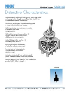
3 Hand clean locally using alcohol based & Certifications Flammability Standards: UL94V 0 for case UL: File No. E44145 All models recognized at 6A @ 125V AC or 3A @ 250V AC or maximum @ 28V DC maximum. Add /U to end of part number to order UL mark on switch. CSA: File No. 023535_0_000 All models recognized at 6A @ 125V AC or 3A @ 250V AC or maximum @ 28V maximum. Add /C to end of part number to order CSA mark on MMiniature PBSlidesProgrammableTogglesBRockersTouch TiltDistinctive CharacteristicsThree methods of panel mounting: flat frame for flush with face or subpanel, snap-in, and insulating barriers increase isolation of circuits in multipole devices and provide added protection to contact points. The molded diallyl phthalate case has a UL 94V-0 flammability rating. Epoxy sealed terminals prevent entry of solder flux and other contaminants.
4 Prominent external insulating barriers increase insulation resistance and dielectric strength. Bias guard prevents misalignment of contacts; interlocking of actuator block with rocker and internal guide does not allow transmission of diagonal force on rocker to reach contact mechanism. Clinching of the frame to the case well above the base and terminals provides 1,500V dielectric SizeFlat Frame Mount Page B83 Bracket PC Mount Page B72 Snap-in Mount Page MBracket PC Mount Miniature RockersB72 IndicatorsAccessoriesSupplementTactilesK eylocksRotariesPushbuttonsIlluminated PBSlidesProgrammableBRockersTouchTilt TogglesIndicatorsAccessoriesSupplementTa ctilesKeylocksRotariesPushbuttonsIllumin ated PBSlidesProgrammableTogglesBRockersTouch TiltBTXTYPICAL SWITCH ORDERING EXAMPLEM20 DPDT ON-NONE-ON CircuitContact Materials & Ratings WSilver; Rated 6A @ 125V AC & 3A @ 250V ACGGold; Rated max @ 28V AC/DC maxAGold over Silver; Rated 6A @ 125V AC & max @ 28V AC/DC maxDESCRIPTION FOR TYPICAL ORDERING EXAMPLEM2022 TZG23-JCTZ Frame with.
5 595 ( )Wide Red RockerTerminals ForTX & TZ FramesStraight PC with Bracket(1-2 Pole only) ( ) Straight PC with .465 ( ) ( ) Straight PC with .630 ( ) ( ) Straight PC with ( ) BracketStraight PC with Reinforced Bracket(1-2 Pole only) ( ) Straight PC with .465 ( ) ( ) Straight PC with .630 ( ) ( ) Straight PC with .953 ( ) BracketGold Contacts with ( ) Straight PC Terminalswith Reinforced BracketRockers& PaddlesSmall Actuators(TX Frame) ( ) Wide ( ) Wide ( ) Wide ( ) Wide PaddleLarge Actuators(TZ Frame) ( ) Wide ( ) Wide PaddleRocker & PaddleColorsABlackBWhiteCRedEYellowFGree nGBlueHGrayG1413 Circuits2 ONNONEON3 ONOFFON5 ONNONE (ON)8(ON)OFF(ON)9 ONOFF(ON)4 ONONON6(ON)ON(ON)7 ONON(ON)( ) = Momentary3-ON circuits**Mounting FramesTXNarrow Frame for Small ActuatorTZWide Frame for Large ActuatorDCDESCRIPTION FOR TYPICAL ORDERING EXAMPLEM2013 TXG41-DCPoles1 SPDT2 DPDTSP3T33 PDT (used only with terminal codes 30 & 41 & frame code TX)44 PDTDP3T(used only with terminal code 41 & frame code TX)Terminals ForTX Frame OnlyRight Angle PC with Support(1-3 Pole only) ( ) Right Angle PCVertical PC with Support(1-4 Pole) ( )
6 Vertical PCSPDT ON-OFF-ON CircuitTX Frame with .365 ( )Wide Red RockerGold Contacts with ( ) Vertical PC Terminals with SupportIMPORTANT: Switches are supplied without UL & CSA marking unless specified. Specific models & ratings noted on General Specifications MBracket PC Mount Miniature PBSlidesProgrammableBRockersTouchTilt TogglesRocker Position( ) = MomentaryConnected TerminalsThrow & SchematicsPoleModelDownCenterUpDownCente rUpSPM2012M2013*M2015M2018*M2019 ONONON(ON)ON NONEOFFNONEOFFOFFONON(ON)(ON)(ON)2-3 OPEN2-1 SPDTDPM2022M2023*M2025M2028*M2029 ONONON(ON)ONNONEOFFNONEOFFOFFONON(ON)(ON )(ON)2-3 5-6 OPEN2-1 5-4 DPDT3PM2022M2023*M2025M2028*M2029 ONONON(ON)ONNONEOFFNONEOFFOFFONON(ON)(ON )(ON)2-3 5-68-9 OPEN2-1 5-48-73 PDT4PM2042M2043*M2045M2048*M2049 ONONON(ON)ONNONEOFFNONEOFFOFFONON(ON)(ON )(ON)2-3 5-68-9 11-12 OPEN2-1 5-48-7 11-104 PDTNote: Terminal numbers are not actually on the switch.
7 * Reverse circuits available for vertical mount SP & DP upon & CIRCUITS111012794613258(COM)25(COM)83164 972 (COM)13461325(COM)For 3 Throw (3-On)Connected Terminals & SchematicsPoleModelDown CenterUpDownCenterUpSPM2024M2026M2027ON( ON)ONONONON ON(ON)(ON)DPM2044M2046M2047ON(ON)ONONONO NON(ON)(ON) 2-3 5-6 2-3 5-4 2-1 5-4 2-3 5-6 2-3 5-4 2-1 5-4 8-9 11-12 8-9 11-10 8-7 11-10 External connection must be made during field SP3T model utilizes a double pole connection must be made during field DP3T model utilizes a four pole base. (out)(out)(out)(out)(out)(out)ExternalCo nnCommon(in)Common(in)124710129635811(ou t)632145(out)(out)ExternalConnCommon(in) 1 (out)4 (out) 6 (out)2 (in)35 External Connection1 (out)4 (out) 6 (out)2 (in)35 External Connection1 (out)4 (out)6 (out)2 (in)35 External Connection1 (out)4 (out) 6 (out) 7 (out)10 (out) 12 (out)8 (in)2 (in)39511 External ConnectionExternal Connection1 (out)4 (out) 6 (out) 7 (out)10 (out) 12 (out)8 (in)2 (in)39511 External ConnectionExternal Connection1 (out)4 (out) 6 (out) 7 (out)10 (out) 12 (out)8 (in)2 (in)39511 External ConnectionExternal ConnectionSeries MBracket PC Mount Miniature PBSlidesProgrammableTogglesBRockersTouch TiltMOUNTING FRAMESN arrow Mounting Frame for Small Actuatorswith Straight PC Terminals (codes 13, 15, 17, 23, 25, & 26)or with Angle PC Terminals (codes 30 & 41)
8 TXSmall Actuators & Panel Cutouts for TX Frame (actuator details on the following pages)CONTACT MATERIALS & RATINGSS ilver over SilverPower Level6A @ 125V AC & 3A @ 250V ACGold over Brass or CopperLogic maximum @ 28V AC/DC maximumNote: See Supplement section to find complete explanation of operating over SilverPower Level or Logic Level6A @ 125V AC or maximum @ 28V AC/DC maximumNote: This dual rated option is suitable when two or more identical switches are used in logic and in power circuits within the same application. See Supplement section to find complete explanation of dual rating and operating Mounting Frame for Large Actuators with Straight PC Terminals (codes 13, 15, 17, 23, 25, & 26)TZStraight PC MountingRight Angle PC MountingVertical PC MountingAT4148AT4149AT4150AT4151 Large Actuators & Panel Cutouts for TZ Frame(actuator details on the following pages)( ).
9 200( ) ( ).315 ( ) ( ) .20025 ( ) Dia .100( ) .17225 ( ) Dia .100( ).138 ( ).235( ).050( ).10825 ( ) Dia .10025 ( ).138( ) Dia .100AT4156AT4157( ).630( ) of Actuation( ).500( ).490 Direction of Actuation( ).398( ).701 Direction of ActuationSeries MBracket PC Mount Miniature PBSlidesProgrammableBRockersTouchTilt TogglesTERMINALSROCKERS & PADDLES FOR TX MOUNTING FRAMESAT4148 .365 ( ) Wide RockerDBlackACap ColorsAvailable:WhiteBRedCYellowEGreenFB lueGMaterial: PolyamideFinish: MatteGrayHAT4149 .365 ( ) Wide PaddleEMaterial: PolyamideFinish: ( ) Terminal ( ) BracketPCB footprints are on the following Typical Switch Dimension ( ) Terminal ( ) ( ) Terminal ( ) ( ) Terminal ( ) ( ) Terminal ( ) ( ) Terminal ( ) BracketFor TX and TZ 1-2 PoleStraight PC Mount with BracketAT4150 .450 ( ) Wide RockerFMaterial: PolyamideFinish: MatteAT4151.
10 450 ( ) Wide PaddleGMaterial: PolyamideFinish: MatteFor TX and TZ 1-2 PoleStraight PC Mount with Reinforced BracketFor TX 1-3 Pole Right Angle PC MountFor TX 1-4 Pole Vertical PC ( ) Right Angle ( ) Vertical PC41( ).093( ).125( ) R .230( ).644( ).138( ).465( ).450( ).248( ).319( ).465( ).362( ).138( ).303( ).450( ).084( ).156( ) R .332( ).138( ).740( ).661( ).365( ).311( ).346( ).242( ).138( ).531( ).664( ).365 Series MBracket PC Mount Miniature PBSlidesProgrammableTogglesBRockersTouch TiltROCKERS & PADDLES FOR TZ MOUNTING FRAMESOPTIONAL SNAP-IN PANEL FRAMESB lackACap ColorsAvailable:WhiteBRedCYellowEGreenFB lueGGrayHAT4156 .595 ( ) Wide RockerJAT4157 .595 ( ) Wide PaddleH( ).263( ) .615( ).705( ).986 ( ).390 ( ).090( ).263( ).765( ) .615 ( ).090( ).472( ).504( ).595( ).433( ).906( ).256( ).331( ).138( ) ( ) .564( ).595( ) ( ) ( ).093( ).187( ) R.