Transcription of NOTES electrical - EVOLVE FURNITURE GROUP
1 52 electrical TECHINCAL INFORMATIONSTEP-BY-STEP SPECIFICATION 8-WIRE electrical SYSTEM Step 1 Determine the location of the source power entering the Panel Run. 1. At the base of the Panel. (a) Use CE8FR1 Reversible Floor Power Entry (default to CE8FR1). (b) Select the Panel to which the Floor Power Entry will be attached. (c) Select the side of the Panel and the receptacle outlet to which the Floor Power Entry is to be attached. Note: When using Pass Through Connectors in conditions other than a straight line, you must use a CE8CI-1 I-Connector along with a CE8CP17 Flexible Mesh Jumper Cable through the corner post.
2 Step 2 Determine which Panels are to be powered. 1. Use CE8PD Power Distribution Housing that corresponds with the width of the 3 Connect power to the powered Panels. 1. Use CE8CP17 Flexible Mesh Jumper Cable between two adjacent powered Panels. 2. Use CE8CP17 Flexible Mesh Jumper Cable between two adjacent powered Panels separated by a post. 3. Use CE8CP17 Flexible Mesh cable (to turn the post) and a CE8CI-1 I Connector to attach the CE8CP Pass Through Cable. (a) The length of the Pass-Through Cable is calculated by adding together the widths of the non-powered Panels that separate the two powered Panels and applying an additional 16 to the total. (CE8PD Power Distri-bution Housing is positioned 8 in from the ends of the powered Panel.) (b) An additional 3 must be added to the Pass-Through Cable for each post that the cable passes through.
3 (c) Subtract 17 from the total length to find the pass through cable length required. 4. From the price list, select the CE8CP Pass-Through Cable that matches the calculated length. If the length is between listed sizes, use the next size 4 Determine the location and circuitry of the receptacles. 1. Each powered Panel has four (4) potential locations for CE8RD Duplex Receptacles 2 per side. (Exception: 24 wide Panel has only two potential locations 1 per side.) 2. At each receptacle location there is a choice of four circuit options. Select a circuit option for each location. Circuits one & two are utility circuits; circuits A & B are dedicated S 8-WIRE electrical SYSTEME lectricalThis modification allows for the integration of the commonly required 2+2 configuration (2 utility circuits, 2 dedicated circuits) found in the source power of most of today s North American system is rated for connection to:1.
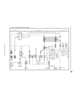
4 A grounded 120/240V, single phase, 20 A, 60Hz2. A 120/208V, 3 phase, 20 A, 60Hz branch circuitData/CommCompile s duplex receptacle openings ( x ) will conform to the ANSI/TIA/EIA FURNITURE Opening Standard of +/- .035 x +/- .04 EQUIPMENT AMPERAGEC alculator .. Eraser .. Sharpener .. - Typewriter .. Computer .. - Display Terminal .. / Letter Quality Printer .. - Printer .. - / Disk - Top Plotter .. - Light .. Projector .. - some equipment, such as large copiers, printers, plotters, heaters and coffee makers would occupy most of the circuit capacity, it is recommended that such devices be supplied with the power directly from the wall or building receptacle. 53 wiring SchematicDefining 2 + 2 wiring Configurations2 + 2 Configuration (8 wire, 4 circuit)Two Utility Circuits [Compile s new #1 & #2 circuits] share one neutral wire and one ground wire.(2 hot [circuit] wires + 1 neutral wire** + 1 green ground wire* = 4 wires)Two Dedicated Circuits [Compile s new A & B circuits] share one neutral wire and one ground wire.
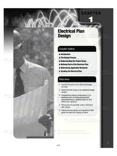
5 (2 hot [circuit] wires + 1 neutral wire ** + 1 green/yellow ground wire** = 4 wires)Note:It is the ground wire that makes the difference between Utility and Dedicated circuits. Refer to wiring Schematics found above.* A Green ground wire is a system ground. This means it could be grounded to any piece of metal, including the Panel.** A Green/Yellow ground wire is isolated, within the wiring conduit, all the way back to the box at the source (building ground).** All Neutral Wires are 10 gauge rather than 12 gauge meaning they are larger than normal, allowing greater protection against noise or interference on the wiring SCHEMATIC54 This page provides an exploded view of a sample configuration highlighting each electrical component required when specifying thisconfiguration.
6 Power Distribution Housing Note: 8 wire, 4 circuits, 2+2 Mesh Jumper Cable (connects two panels side by side or separated by a post) I CableNote: Must run in a straight line application onlyNote: Pass-Through Extension Cable (CE8 CPF154) available extends power capability beyond 208".DCBAEBELECTRICAL 55E8PD - POWER DISTRIBUTION HOUSING Power housing is specified per panel size ( CE8PD36 is for use in a 36 panel). 8 wire, 4 circuits (4th circuit dedicated). Power distribution housing is required for each powered panel, the power distribution housing should equal the width of the panel that it is specified in. Provides two duplex receptacle ports per panel side on all panel widths except the 24 wide panel. 24 wide panel allows for only one (1) duplex receptacle on one panel side. Each power distribution housing supports 15-20 amps. Must specify Raceway Cover with Knockouts on panels, where Power Distribution Housings will be utilized.
7 DESCRIPTION PRODUCT CODE LIST PRICE DIMENSIONS/INCHES H W D Power Distribution Housing CE8PD24 115 6 1 4 CE8PD30 155 11 1 2 CE8PD36 163 17 1 2 CE8PD42 166 23 1 2 CE8PD48 179 29 1 2 CE8PD54 180 39 1 4 CE8PD60 181 41 1 2 CE8PD66 195 51 1 4 CE8PD72 206 57 1 4CE8CP17 - FLEXIBLE MESH JUMPER CABLE 17 mesh jumper.
8 Jumper cable is used to pass through a post or connect two panels together. DESCRIPTION PRODUCT CODE LIST PRICE DIMENSIONS/INCHES H W D Flexible Mesh Jumper Cable CE8CP17 88 17 electrical 56 CE8CP - PASS THROUGH CABLE Flexible metal conduit is used to distribute electrical power through non-powered panels. Metal conduit pass through cables should be in used in a straight runs.
9 Metal conduit pass through cables cannot pass through a post. Flexible conduit is required to turn a post. This only comes as 17 w. If panels at the posts do not all have power distribution housings, they must be added even if duplexes are not specified. To calculate the length of a Pass-Through Cable, add the widths of the non-powered panels separating the powered panels (panels with distribution housing attached). To this add 16 (distance from the edge of the panel to the distribution housing x 2). Add additional 3 when passing through a corner post. See the Tips at the beginning of the section for more details. DESCRIPTION PRODUCT CODE LIST PRICE DIMENSIONS/INCHES H W D Pass Through Cable CE8CP28 117 28 1 2 CE8CP40 124 40 1 2 CE8CP46 127 46 1 2 CE8CP52 131 52 1 2
10 CE8CP58 139 58 1 2 CE8CP64 146 64 1 2 CE8CP70 150 70 1 2 CE8CP76 152 76 1 2 CE8CP82 158 82 1 2 CE8CP88 163 88 1 2 CE8CP94 167 94 1 2 CE8CP100 173 100 1 2