Transcription of Chapter 8 Automotive Electrical Circuits and Wiring
1 Chapter 8 Automotive Electrical Circuits and Wiring Topics Charging circuit Starting circuit Safety Switches Ignition System Lighting circuit Instruments, Gauges, and Accessories Automotive Wiring To hear audio, click on the box. Overview The Electrical systems on equipment used by the Navy are designed to perform a variety of functions. The Automotive Electrical system contains five Electrical Circuits : charging, starting, i gnition, l ighting, and accessory. Electrical power and control signals must be delivered to Electrical devices reliably and safely. This goal is accomplished through careful circuit design, prudent component selection, and practical equipment location. By carefully studying this Chapter , you will understand how these Circuits work and the adjustments and repairs required to maintain the Electrical systems in peak condition.
2 Objectives When you have completed this Chapter , you will be able to do the following: 1. Identify charging- circuit components, their functions, and maintenance procedures. 2. Identify starting- circuit components, their functions, and maintenance procedures. 3. Identify ignition- circuit components, their functions, and maintenance procedures. 4. Identify lighting- circuit components, their functions, and maintenance procedures. 5. Identify instruments, gauges, and accessories, their functions, and maintenance procedures. 6. Identify the basic types of Automotive Wiring , types of terminals, and Wiring diagrams. NAVEDTRA 14264A8-1 Prerequisites This course map shows all of the chapters in Construction Mechanic Basic. The suggested training order begins at the bottom and proceeds up.
3 Skill levels increase as you advance on the course map. Automotive Chassis and Body C Brakes M Construction Equipment Power Trains Drive Lines, Differentials, Drive Axles, and Power Train Accessories Automotive Clutches, Transmissions, and Transaxles Hydraulic and Pneumatic Systems Automotive Electrical Circuits and Wiring B A Bas ic Automotive Electricity S Cooling and Lubrication Systems I Diesel Fuel Systems C Gasoline Fuel Systems Construction of an Internal Combustion Engine Principles of an Internal Combustion Engine Technical Administration Features of this Manual This manual has several features which make it easy to use online. Figure and table numbers in the text are italicized.
4 The figure or table is either next to or below the text that refers to it. The first time a glossary term appears in the text, it is bold and italicized. When your cursor crosses over that word or phrase, a popup box displays with the appropriate definition. Audio and video clips are included in the text, with italicized instructions telling you where to click to activate it. Review questions that apply to a section are listed under the Test Your Knowledge banner at the end of the section. Select the answer you choose. If the answer is correct, you will be taken to the next section heading. If the answer is NAVEDTRA 14264A8-2incorrect, you will be taken to the area in the Chapter where the information is for review. When you have completed your review, select anywhere in that area to return to the review question.
5 Try to answer the question again. Review questions are included at the end of this Chapter . Select the answer you choose. If the answer is correct, you will be taken to the next question. If the answer is incorrect, you will be taken to the area in the Chapter where the information is for review. When you have completed your review, select anywhere in that area to return to the review question. Try to answer the question again. NAVEDTRA CHARGING circuit The basic charging system consists of a battery, alternator, voltage regulator, ignition switch, and indicator light or indicator gauge or both. They must all work together to provide a source of electricity for the vehicle to operate. The charging system performs several functions: It recharges the battery after engine cranking or after the use of Electrical accessories with the engine turned off.
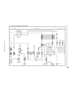
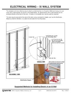
6 It supplies all the electricity for the vehicle when the engine is running. It must change output to meet different Electrical loads. It provides a voltage output that is slightly higher than battery voltage. Storage Battery The storage battery is the heart of the charging circuit (Figure 8-1). It is an electrochemical device for producing and storing electricity. A vehicle battery has several important functions: It must operate the starting motor, ignition system, electronic fuel injection system, and other Electrical devices for the engine during engine cranking and starting. It must supply all of the Electrical power for the vehicle when the engine is not running. It must help the charging system provide electricity when current demands are above the output limit of the charging system.
7 It must act as a capacitor (voltage stabilizer) that smoothes current flow through the Electrical system. It must store energy (electricity) for extended periods. The type of battery used in Automotive , construction, and weight-handling equipment is a lead-acid cell-type battery. This type of battery produces direct current (DC) electricity that flows in only one direction. When the battery is discharging, it changes chemical energy into Electrical energy, thereby, releasing stored energy. During charging (current flowing into the battery from the charging system), Electrical energy is converted into chemical energy. The battery can then store energy until the vehicle requires it. Battery Construction The lead-acid cell-type storage battery is built to withstand severe vibration, cold weather, engine heat, corrosive chemicals, high current discharge, and prolonged periods without use.
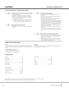
8 To test and service batteries properly, you must understand battery construction. The construction of a basic lead-acid cell-type battery is as follows: Figure 8-1 Battery. NAVEDTRA 14264A8-4 Battery element Battery case, cover, and caps Battery terminals Electrolyte The battery element is made up of negative plates, positive plates, separators, and straps (Figure 8-2). The element fits into a cell compartment in the battery case. Most Automotive batteries have six elements. Each cell compartment contains two kinds of chemically active lead plates, known as positive and negative plates. The battery plates are made of a stiff mesh framework coated with porous lead. These plates are insulated from each other by suitable separators and are submerged in a sulfuric acid solution (electrolyte).
9 Charged negative plates contain spongy (porous) lead (Pb), which is gray in color. Charged positive plates contain lead peroxide (PbO2), which has a chocolate brown color. These substances are known as the active materials of the plates. Calcium or antimony is normally added to the lead to increase battery performance and to decrease gassing. Since the lead on the plates is porous like a sponge, the battery acid easily penetrates into the material. This aids the chemical reaction and the production of electricity. Lead battery straps or connectors run along the upper portion of the case to connect the plates. The battery terminals (post or side terminals) are constructed as part of one end of each strap. To prevent the plates from touching each other and causing a short circuit , sheets of insulating material ( micro-porous rubber, fibrous glass, or plastic impregnated material), called separators, are inserted between the plates.
10 These separators are thin and porous so the electrolyte will flow easily between the plates. The side of the separator that is placed against the positive plate is grooved so the gas that forms during charging will rise to the surface more readily. These grooves also provide room for any material that flakes from the plates to drop to the sediment space below. The battery case is made of hard rubber or a high- quality plastic. The case must withstand extreme vibration, temperature change, and the corrosive action of the electrolyte. The dividers in the case form individual containers for each element. A container with its element is one cell. Stiff ridges or ribs are molded in the bottom of the case to form a support for the plates and a sediment recess for the flakes of active material that drop off the plates during the life of the battery.