Transcription of Wind Turbine Control - University of Notre Dame
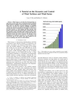
1 Summary Chapter 6-End1 wind Turbine Control The Control system on a wind Turbine is designed to:1. seek the highest efficiency of operation that maximizes thecoefficient of power,Cp,2. ensure safe operation under all wind conditions. wind Turbine Control systems are typically divided into threefunctional elements:1. the Control of groups of wind turbines in a wind farm,2. the supervising Control of each individual wind Turbine , and3. separate dedicated dynamic controllers for different wind tur-bine sub-systems. Generally, there exists anoptimumtip-speed-ratio, thatmaximizedCp.
2 The exact depends on the individual wind Turbine design(6 8) University of Notre DameAME 40530 Summary Chapter 6-End2 Figure 1: Example of the relation between the rotor tip-speed ratio and rotor pitch angle onthe coefficient of power for a 600kW two-bladed horizontal wind Turbine . The sensitivity ofCpto motivates closed-loop Control focusingon the the rotation frequencyFigure 2: Schematic of a wind Turbine closed-loop Control of Notre DameAME 40530 Summary Chapter 6-End31 Axial Induction ControlRecall that the rotor blade tip speed ratio, is = RU.
3 (1)The power generated from the wind isPaero=Q (2)whereQis the total torque generated by the coefficient of power,Cp, is the ratio of the aerodynamic powerextracted from the wind and the available aerodynamic power or,Cp=Paero/Pavailable.(3)The local axial and tangential induction factors are defined asa= 1 UxU (4)anda =Uy r 1(5)whereUxandUyare the respective axial and tangential velocities inthe rotor local flow angle at a given radial location on the rotor is then r= tan 1 UyUx = tan 1 U (1 a) r(1 +a ) = tan 1 (1 a)(1 +a ) r (6)where ris the local tip speed ratio at the radial position, local effective rotor angle of attack at any radial location isthen r= r r (7)
4 University of Notre DameAME 40530 Summary Chapter 6-End4where ris again the local flow angle, ris the local rotor twistangle, and is the global rotor pitch angle which is constant over therotor local lift and drag coefficients,Cl(r) andCd(r), at a radiallocation on the rotor are thenCl(r) =Cycos( r) Cxsin( r)(8)andCd(r) =Cysin( r) +Cxcos( r)(9)whereCxandCyare the force coefficients in the tangential andnormal directions of the rotor section at the effective angle of attack, differential torque produced by radial segment of the rotor atradius,r, isdQ= 4 U ( r)a (1 a)r2dr 12 W2 NcCdcos( r)rdr.
5 (10)To simplify, the second term in Equation 10 is dropped (neglectingthe drag on the rotor). The differential torque is thendQ= 4 U ( r)a (1 a)r2dr.(11)Substituting fora in terms ofagivesdQ= 4 U2 a(1 a)2r2 dr.(12)Assuming constant wind conditions ( andV ) and a fixed tip speedratio, , thendQ=C1a(1 a)2r2dr.(13)Assuming the axial induction factor is constant along the entirerotor span,Q a(1 a)2.(14) University of Notre DameAME 40530 Summary Chapter 6-End5In terms of the aerodynamic power,Paero=Q (15)orPaero a(1 a)2.(16) University of Notre DameAME 40530 Summary Chapter 6-End6 wind FarmsFigure 3: Schematic drawing of wind Turbine wake model.
6 The local downstream wake radius isr1given asr1= x+rr(17) r0is the physical radius of the upstream wind Turbine rotor is the wake entrainment constant, also known as the wakedecay constant, where = (zz0)(18)wherezis the wind Turbine hub height, andz0is the surfaceroughness height at the site. rris the effective radius of the upstream wind Turbine rotorgiven asrr=r0 1 a1 2a.(19) University of Notre DameAME 40530 Summary Chapter 6-End7 Ifiis designated as the position of the wind Turbine producingthe wake, andjis the downstream position that is affected bythe wake, then the wind speed at positionjisuj=u0(1 udefij)(20) whereudefijis thewake velocity deficitinduced on positionjby an upstream wind Turbine at positioni.
7 Thewake deficitcan be computed through the following re-lationudefij=2a1 + (xijrr)2(21) whereais the inflow induction factor that is related to thewind Turbine thrust coefficient,CTasa= (1 1 CT)(22) xijis the downstream distance between of Notre DameAME 40530 Summary Chapter 6-End8 wind Farm Design OptimizationFigure 4: Impact of site area and number of wind turbines on wind farm of Notre DameAME 40530 Summary Chapter 6-End92 wind Turbine Acoustics Thesound pressure levelof a source in units of decibels(dB), is given asLP= 20 log10(Prms/P0)(23) Prmsis the root-mean-square of the pressure fluctuations, P0is the reference threshold sound pressure level,P0= 2 10 Sound Pressure Measurement and Weighting A-scale Weighting, is the most common scale for assessingenvironmental and occupational noise.
8 It approximates the re-sponse of the human ear to sounds of medium intensity. B-scale Weighting, approximates the response of the humanear for medium-loud sounds, around 70 dB. (not commonly used) C-scale Weighting, approximates the response of the humanear to loud sounds. (Can be used for low-frequency sound) G-scale Weighting, used for ultra-low frequency, of Notre DameAME 40530 Summary Chapter dB Math The sum of two sound sources of 90 dB and 80 dB, in decibels, is90dB = 20 log(P 902 10 5Pa)= (24)80dB = 20 log(P 802 10 5Pa)= (90 + 80)dB = 20 log( 10 5Pa)= of Notre DameAME 40530 Summary Chapter wind Turbine Sound SourcesFigure 5: Mechanisms for sound generation due to the air flow over the Turbine 6.
9 Sound level power scaling for different aerodynamic sound source mechanisms onthe Turbine of Notre DameAME 40530 Summary Chapter 6-End12 Figure 7: Sound pressure level azimuthal radiation pattern for a wind of Notre DameAME 40530 Summary Chapter Sound Propagation Asimple modelbased on the more conservative assumptionof hemispherical sound propagation over a reflective surface, in-cluding air absorption isLp=Lw 10 log10(2 R2) R(25) Lpis the sound pressure level (dB) a distanceRfrom a soundsource radiating at a power level,Lw, (dB), = dB/m is the frequency-dependent sound absorp-tion Noise StandardsTable 1.
10 ISO 1996-1971 Recommendations for Community Noise LimitsLocationDaytime - db(A)Evening - db(A)Night - dB(A)7AM-7PM7PM-11PM11PM-7 AMRural353025 Suburban403530 Urban Residential454035 Urban Mixed504540 University of Notre DameAME 40530 Summary Chapter 6-End143 wind Turbine Energy StorageFigure 8: Example of a two week period of system loads, system loads minus wind generation,and wind 9: Comparison of different electric power storage systems with regard to power ratingand discharge of Notre DameAME 40530 Summary Chapter Battery Case Study Erated=CratedVnominal[W h](26) Cratedis the amp-hour capacity of the battery Vnominalis the nominal voltage of the battery General restriction on the depth of discharge (DOD) of50% of capacityto ensure a long operating life usable energy of a deep-cycle lead acid batteryin whichVnominal= 60V, andCrated= 1200A-hr isEusable=Erated DOD(27)= (1200)(60)( )