Transcription of PT Activity 3.6.1: Packet Tracer Skills Integration Challenge
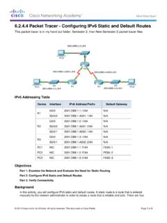
1 PT Activity : Packet Tracer Skills Integration Challenge Topology Diagram All contents are Copyright 2008 Cisco Systems, Inc. All rights reserved. This document is Cisco Public Information. Page 1 of 8 CCNA Exploration Accessing the WAN: Frame Relay PT Activity : Packet Tracer Skills Integration Challenge All contents are Copyright 2008 Cisco Systems, Inc. All rights reserved. This document is Cisco Public Information. Page 2 of 8 Addressing Table Device Interface IP Address Subnet Mask S0/0/1 HQ S0/0/0 S0/0/0 WEST Fa0/0 S0/0/0 Fa0 Fa0 Fa0 SOUTH Fa0 S0/0/0 EAST Fa0/0
2 S0/0/0 ISP Fa0/0 Web Server NIC S1 VLAN99 S2 VLAN99 S3 VLAN99 Learning Objectives Configure PPP with CHAP. Configure full mesh Frame Relay. Configure static and default routing. Configure and test inter-VLAN routing. Configure VTP and trunking on switches. Configure VLANs on a switch.
3 Configure and verify interface VLAN 99. Configure a switch as root for all spanning trees. Assign ports to VLANS. Test end-to-end connectivity. Introduction This Activity allows you to practice a variety of Skills , including configuring Frame Relay, PPP with CHAP, static and default routing, VTP, and VLAN. Because there are close to 150 graded components in this Activity , you may not see the completion percentage increase every time you configure a graded command. You can always click Check Results and Assessment Items to see if you correctly entered a graded command.
4 Use the passwords cisco and class to access EXEC modes of the CLI for routers and switches. CCNA Exploration Accessing the WAN: Frame Relay PT Activity : Packet Tracer Skills Integration Challenge All contents are Copyright 2008 Cisco Systems, Inc. All rights reserved. This document is Cisco Public Information. Page 3 of 8 Task 1: Configure PPP with CHAP Between Devices Step 1. Configure and activate serial 0/0/1 on HQ. Step 2. Configure PPP encapsulation on HQ for the link shared with ISP. Step 3. Configure CHAP authentication on HQ. Use cisco as the password.
5 Step 4. Verify connectivity between HQ and ISP. The link between HQ and ISP should now be up, and you should be able to ping ISP. However, the link may take a few minutes in Packet Tracer before it comes up. To speed up the process, switch between Simulation and Realtime mode three or four times. Step 5. Check results. Your completion percentage should be 4%. If not, click Check Results to see which required components are not yet completed. Task 2: Configure Full Mesh Frame Relay The above topology diagram and the table below both show the DLCI mappings used in this full mesh Frame Relay configuration.
6 Read the table from left to right. For example, the DLCI mappings you will configure on HQ are: 102 to WEST; 103 to SOUTH; and 104 to EAST. DLCI Mappings From/To HQ WEST SOUTH EAST HQ N/A 102 103 104 WEST 201 N/A 203 204 SOUTH 301 302 N/A 304 EAST 401 402 403 N/A Note: HQ, WEST, and SOUTH are all using the default Frame Relay encapsulation cisco.
7 However, EAST is using the encapsulation type IETF. Step 1. Configure and activate the serial 0/0/0 interface on HQ. Configure the interface with the following information: IP address Frame Relay encapsulation Mappings to WEST, SOUTH, and EAST (EAST uses IETF encapsulation) LMI type is ANSI Step 2. Configure and activate the serial 0/0/0 interface on WEST. Configure the interface with the following information: IP address Frame Relay encapsulation Mappings to HQ, SOUTH, and EAST (EAST uses IETF encapsulation) LMI type is ANSI CCNA Exploration Accessing the WAN: Frame Relay PT Activity : Packet Tracer Skills Integration Challenge All contents are Copyright 2008 Cisco Systems, Inc.
8 All rights reserved. This document is Cisco Public Information. Page 4 of 8 Step 3. Configure and activate the serial 0/0/0 interface on SOUTH. Configure the interface with the following information: IP address Frame Relay encapsulation Mappings to HQ, WEST, and EAST (EAST uses IETF encapsulation) LMI type is ANSI Step 4. Configure and activate the Serial 0/0/0 interface on EAST. Configure the interface with the following information: IP address Frame Relay encapsulation using IETF Mappings to HQ, WEST and SOUTH LMI type is ANSI Note: Packet Tracer does not grade your map statements.
9 However, you must still configure the commands. You should now have full connectivity between the Frame Relay routers. Step 5. Verify connectivity between Frame Relay routers. The map on HQ should look like the following. Make sure all routers have full maps. Serial0/0/0 (up): ip dlci 102, static, broadcast, CISCO, status defined, active Serial0/0/0 (up): ip dlci 103, static, broadcast, CISCO, status defined, active Serial0/0/0 (up): ip dlci 104, static, broadcast, IETF, status defined, active Verify that HQ, WEST, SOUTH, and EAST can now ping each other.
10 Step 6. Check results. Your completion percentage should be 28%. If not, click Check Results to see which required components are not yet completed. Task 3: Configure Static and Default Routing No routing protocol is used in this topology. All routing is done through static and default routing. Step 1. Configure static and default routes on HQ. HQ needs six static routes to the six remote LANs in the topology. Use the next-hop-ip argument in the static route configuration. HQ also needs a default route. Use the exit-interface argument in the default route configuration.