Transcription of Temperature Dependency of Zener Voltage
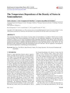
1 VISHAY SEMICONDUCTORSZ ener and Suppressor DiodesApplication NoteTemperature Dependency of Zener VoltageAPPLICATION NOTE Document Number: 84810 For technical questions within your region, please contact one of the : Fig. 1 - Zener Voltage Change vs. Pulse DurationThe Zener Voltage (VZ) of a Zener or avalanche diode depends on the diode s junction current running through the p/n junction barrier generates the electrical power of: P = IZ * VZThis electrical power is equivalent to the thermal power applied to this junction. Depending on the duration and the intensity ofthe current, the applied thermal energy increases and heats the junction. The upper diagram shows the Zener Voltage changeof a BZX85C43 Z-Diode in a DO-41 wired glass package during a constant current pulse. The diode is mounted between largeheat sinks (copper blocks) with a stable Temperature of 25 1: Internal warm up phaseThe current starts to heat the silicon of the p/n junction and charge the caloric capacitance of the material around the heat moves from the warm junction through the silicon chip to the metal contact inside the glass package to the terminalsof the wire.
2 With the rising Temperature , the Zener Voltage increases according to the Temperature coefficient (TC).Thermal EquilibriumInternal warm up phaseExternal warm up VZener Voltage Iz = 10mAIz = 5mATAmbient (heat sink) = 25 s1 s10 s100 sPulse dura onIz = 1mABACDT hermal coupling: Diode position between the heat sinksBADCBADCBADCI zpulsedV z22268 Temperature Dependency of Zener VoltageApplication NoteVishay SemiconductorsAPPLICATION NOTE Document Number: 84810 For technical questions within your region, please contact one of the : 2: External warm up phaseThe heat leaves the package and moves through the wires to the heat sink. In contrast to phase 1, during phase 2 thermalresistance can be influenced by the customer. The shorter the wires, the lower the additional thermal resistance to the heat sinkwith defined low Temperature and vice 3: The thermal equilibriumThe material along the following thermal path from the junction to the heat sink is now completely charged up; the junctiontemperature and thus the Zener Voltage are now diagram shows that the test conditions are important in defining the Zener Voltage of a Zener diode: the Zener test current IZ the junction Temperature right before the pulse test the point in time during the current pulse at which the Voltage is measured the junction-to-ambient thermal resistance.


![C = Q/ T = dQ/dT [J/deg] - University of Virginia](/cache/preview/a/f/5/8/1/b/f/3/thumb-af581bf37b8258665c1595c6c7b2f7a3.jpg)


