Transcription of 28V MIL-COTS VIPAC - Vicor Corporation
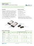
1 28 VDC MIL-COTS VIPAC Rev 1 of 6 11/2016 800 & Benefits DC input : 28 VDC Output voltages: n 48 VDC n 40 400W total n 1, 2, or 3 outpu ts Protective features: n Inrush current limiting n input transient protection: per MIL-STD-704E/F (M-FIAM5B) per MIL-STD-704A/E/F & MIL-STD-1275A/B/D (M-FIAM9) n EMI filtering per MIL-STD-461E Local or remote control Compliant to MIL-STD-810F for vibration (Method , Procedure I) and shock (Method , Procedure I) Module environmental stress screening Package style: n Low profile mounting options n Optional finned heat sinkProduct HighlightsThe 28 VDC MIL-COTS VIPAC family of power systems is a new class of user-defined, modular power solutions for the most demanding military applications.
2 It incorporates preassembled and tested front ends (M-FIAM5B or M-FIAM9), Vicor Maxi, Mini and Micro series DC-DC converters (H or M-Grade), a choice of output connections and mechanical platforms. The 28 VDC VIPAC can be specified with 1, 2 or 3 outputs with voltages as low as to as high as 48 VDC and power levels from 40 to 400W per output. Additionally, the wide trim range of the modules can provide operating voltages from 500mv to The MIL VIPAC is available with an input of 28 VDC in a variety of packages with profiles as low a s 0.
3 7 5 .For additional technical or design information; or to create a 28 VDC VIPAC tailored to your specific requirements using Vicor s online configurator, please visit x (126,0 x 172,7mm) lbs (640g) Dual or triple output Up to 300W3 Micros (MVC-Axxx, MVX-Axxx) x (126,0 x 172,7mm) lbs (640g) Single or dual output Up to 400W2 Minis (MVC-Bxxx, MVX-Bxxx) x (80,0 x 172,7mm) lbs (411g) Single output Up to 100W1 Micro (MVC-Gxxx, MVX-Gxxx) x (80,0 x 172,7mm) lbs (457g) Single or dual output Up to 200W2 Micros (MVC-Dxxx, MVX-Dxxx)
4 X (80,0 x 172,7mm) lbs (457g) Single output Up to 200W1 Mini (MVC-Exxx, MVX-Exxx) x (80,0 x 234,4mm) lbs (594g) Single output Up to 400W1 Maxi (MVC-Fxxx, MVX-Fxxx)Note: Weights are for coldplate versions MVC-xxx refers to M-FIAM5B MVX-xxx refers to M-FIAM928 VDC MIL-COTS VIPACLow Profile, Configurable Power Solution28 VDC MIL-COTS VIPAC Rev 2 of 6 11/2016 800 VIPAC General SpecificationsTypical at 25 C, nominal line and load, unless otherwise SPECIFICATIONSP arameter Min Typ Max Unit NotesInput voltage 18 28 36 VDC ContinuousInrush limiting A/ F Transient immunity (M-FIAM5B)
5 50 VDC per MIL-STD-704E/F, continuous operation Test conditions AA and FF normal overvoltage transients per MIL-HDBK-704 Transient immunity (M-FIAM9) 100 VDC 50ms per MIL-STD-1275A/B/D, continuous operation 250 VDC 70 s per MIL-STD-1275A/B/D, continuous operation 70 VDC 20ms per MIL-STD-704A, continuous operation 50 VDC per MIL-STD-704E/F, continuous operationEMI MIL-STD-461E Conducted emissions CE101.
6 CE102* Conducted susceptibility CS101, CS114, CS115, CS116 ENVIRONMENTAL - SYSTEMP arameter Min Typ Max Unit Notes Dielectric withstand, input to chassis 1500 / 2121 VRMS/VDC Operating chassis temperature H-Grade -40 95 C M-Grade -55 95 C Storage temperature H-Grade -55 125 C M-Grade -65 125 C Shock MIL-STD-810F, Method , Procedure I 40g for 15-23ms.
7 75g for 8-13msVibration MIL-STD-810F, Method , Procedure I 20-2000Hz at 5gOUTPUT SPECIFICATIONSP arameter Min Typ Max Unit Notes Output voltage setpoint 1 % VOUT nom Line regulation % Low line to high line; full load Temperature regulation %/ C Over operating temperature rangeOver temperature shutdown 115 C Power sharing accuracy 2 5 % Programming range 10 110 % Of nominal voltage.
8 (For trimming below 90% of nominal, a minimum load of 10% rated power may be required)Current limit 115 % IOUT max Output voltage 95% of nominalShort circuit current 115 % IOUT max Output voltage < 250mV*CE102 compliant with loads in excess of 30% of rated output; loads below 30% may need additional input capacitance for VDC MIL-COTS VIPAC Rev 3 of 6 11/2016 800 VIPAC SPECIFIC SpecificationsENVIRONMENTAL - MODULESMIL- cots 28 VDC VIPAC OUTPUT POWER OPTIONS (OUTPUT POWER BASED ON 28 VDCC NOMINAL input VOLTAGE)AltitudeMIL-STD-810C, Method , Procedure I & II, 40,000 ft.
9 And 70,000 ft. AtmosphereMIL-STD-810F, Method , Procedure I, , Method , Procedure I, Category 14, Sine and Random vibration per Table for Helicopter AH-6J Main Rotor with overall level of Grms for 4 hours per axis. MIL-STD-810F, Method , General Minimum Integrity Curve per Figure with overall level of Grms for 1 hour per , Method , Procedure I, Functional Shock, 40 G s. MIL-S-901D, Lightweight Hammer Shock, 3 impacts/axis, 1,3,5 ft. MIL-STD-202F,Method 213B, 60 G s, 9ms half sine. MIL-STD-202F, Method 213B, 75 G s, 11ms Saw Tooth , Method , Procedure II, Table , Operational, 2-7 G s, 6 , Method , Procedure I, Cycle I, 240 hrs, 95% TestMIL-STD-202F, Method 208, 8 hour MIL-COTS VIPAC Derating Curve288400~~0 Safe Operating AreaOutput Power (W)Tr ansientVinInput Voltage (V)Derate @ 16 W/V Below 25 Vin102030405060182536// = parallel1 Lower power modules available consult website for more Derate outpower per chart below.
10 Power (W) VIPAC Configuration No. of Outputs V 5 V 12 V 15 V 24 V 28 V 48 V Total2 Single micro1 Single 75 100 100 100 100 100 100 100 Single // 150 200 200 200 200 200 200 200 Dual micro1 Dual 75 100 100 100 100 100 100 200 75