Transcription of INSTALLATION GUIDE - webtools.schierproducts.com
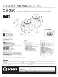
1 INSTALLATION GUIDEM odel #GB-250 100/200 GPM Grease InterceptorFor Indoor/Outdoor UseContentsSpecial Precautions .. 2 General INSTALLATION Instructions .. 3 Field Cut Riser INSTALLATION Guidelines .. 4 Anchor Kit INSTALLATION .. 4 Expanding Grease Capacity .. 5 Application Specific Details .. 6 Document #: 057-0780-04 Find these instructions online at: 2 of 6 When Installing Interceptor InsideIf your dishwashing sink(s) discharges into a floor drain/sink (drain), you must regulate the flow into the drain to avoid an overflow of water onto the kitchen floor. This can be done by installing a valve or flow restriction cap on the sink piping that discharges into the drain. See drawing above for guidance. For detailed guidance on indirect connections, go to: PRECAUTIONSFor All Schier Grease Interceptor Installations - Failure to follow this guidance voids your warranty High Water Table InstallationsInterceptors and risers are not designed to withstand water table height in excess of the top of the unit when buried (see figure).
2 If it is possible for this to occur, install the interceptor and risers in a water-tight concrete vault or backfill with concrete or flowable fill (wet concrete and flowable backfill should be poured in stages to avoid crushing the interceptor). At risk areas include but are not limited to tidal surge areas, floodplains and areas that receive storm water. Models GB-50, GB-75, and GB-250 that are direct buried in high water table scenarios must be installed with model AK1 anchor water table height for direct burialmodel AK1 anchor kitFully Support Base of Unit Install unit on solid, level surface in contact with the entire footprint of unit base; for suspended installations design trapeze to support the wet weight of the unit. Do not partially support unit or suspend unit using metal U-channel to create a trapezeInstallation InstructionsInstallation instructions and additional components are included with the interceptor.
3 Read all instructions prior to INSTALLATION . This interceptor is intended to be installed by a licensed plumber in conformance with all local floorsuspended installationFernco or similar rubber flow restriction end capHydrostatic Slabs (or Pressure Slabs) When installed under a hydrostatic slab (slab designed to withstand upward lift, usually caused by hydrostatic pressure) interceptor must be enclosed in a watertight concrete vault. InterceptorInterceptorInterceptorconcret e slab subject to hydrostatic pressure watertight concrete vault Support Inlet and Outlet Piping For above grade installations ensure heavy inlet and outlet piping (such as cast iron or long runs) is properly supported or suspended during the entire INSTALLATION process to prevent connection failure or damage to bulkhead fittings. InterceptorInterceptorInterceptorpipe supportsHigh Temperature Kitchen Water If water is entering the interceptor at excessive temperature (over 140 F), a drain water tempering valve (DTV) and approved backflow prevention assembly must be installed.
4 Most state and local plumbing codes prohibit water above 140 F being discharged into the sanitary sewer. Water above 140 F will weaken or deform PVC Schedule 40 pipe, poly drainage fixtures like interceptors and erode the coating of cast iron (leading to eventual failure).InterceptorInterceptorIntercept orcold water supply linehigh temperature effluent ( > 140 F)approved backflow prevention assemblyDTV (drain water tempering valve)directly connectedindirectly connectedInterceptorInterceptorIntercept orinstallation instructions057-0780-04page 3 of 6 LEAK/SEAL TESTINGCap/plug all base unit plumbing connections and remove covers. For base unit testing , fill with water to just above the highest connection. For riser system testing (if required) fill with water to finished grade level. CAUTION: Risers must be supported before filling with water to prevent tipping.
5 Inspect unit, connections and all gaskets and clamps (if applicable) for leaks. Check water level at specific time intervals per local INSTALLATION INSTRUCTIONSS chier grease interceptors are manufactured with an internal flow control system. They do not require an external flow control system or air intake vent. Schier grease interceptors are not to be installed in any other manner except as shown. Consult local codes for separate trapping requirements, cleanout locations and additional INSTALLATION Flow control is not pre-installed on this unit - two flow control plates are provided in a bag fastened to the neck of the unit (for either 100 or 200 GPM). When unit is installed 13 feet or more below fixtures being served, or a high flow/increased head pressure condition exists (causing a flow rate above the desired flow rate), install the appropriate inlet diffuser flow control plate to maintain proper flow rate.
6 2. Set unit on level solid surface as close as possible to fixtures being served. 3. Connect outlet diffuser to the desired outlet (A,B,C). Unit is shipped with the outlet diffuser in location B and sealing caps on locations A and C. Fixed outlet models (-FO) have outlet diffuser permanently welded at the factory in the straight-through (B) Connect inlet and outlet drainage lines to unit. Mechanically couple pipes to unit. Do not solvent weld. 5. For unit with cast iron covers, remove retainer clips prior to : Do not install below a hydrostatic GRADE INSTALLATION INSTRUCTIONSEXCAVATION1. Surrounding soil must be undisturbed soil or well compacted engineering fill. 2. Width and length of excavation shall be a minimum of 12" greater than the tank on all sides and depth shall be 6" deeper than tank bottom. 3. Set the tank level on a 6" deep layer of well-packed crushed aggregate material and connect waste piping per General INSTALLATION 1.
7 Preparation of sub grade per geotech recommendations. 2. Stabilize and compact sub grade to 95% proctor. 3. Fill unit with water before backfilling to stabilize unit and prevent float-out during backfilling. Secure covers and risers (if necessary) to the Backfill evenly around tank using crushed aggregate (approximately 3/4" size rock or sand, with no fines), or flowable fill. Do not compact backfill around unit. FINISHED CONCRETE SLABSlab must extend 18" minimum outside the footprint of the traffic or greenspace areas: 4" Thick reinforced concrete slab traffic areas: Minimum 8" Thick concrete slab with rebar required. Thickness of concrete around cover to be determined by specifying engineer. If traffic loading is required the concrete slab dimensions shown are for guideline purposes only. Concrete to be 28 day compressive strength to 4,000 PSI.
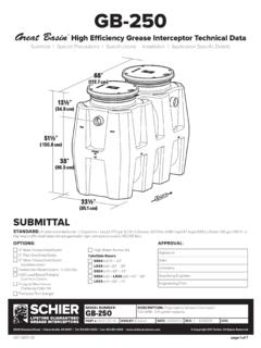
8 Use NO. 4 rebar ( 1/2") grade 60 steel per ASTM A615: connected with tie wire. Rebar to be 2-1/2" from edge of concrete and spaced in a 12" grid with 4" spacing around access ! DO NOT AIR TEST UNIT OR FIELD CUTRISER SYSTEM! Doing so may result in property damage, personal injury or AND BACKFILL DETAILFLOW CONTROLPLATE DETAILO ptional anchor kitOptional anchor kitRisers to GradeNative soilBackfillWell packed baseConcrete slabFinished gradeAdapterRiserRecommended 2-Way cleanout tee to grade (by others)Finished gradeFinished grade4"8" (Vehicular traffic)TOP VIEWELEVATION VIEWCONCRETE SLAB DETAILR ebar18"min18"min18" min45 18" min RebarConcrete Slab4"Thick for pedestrian8" Thick for vehicularSIDE VIEW DETAILOR200 GPM100 " " 057-0780-04 INSTALLATION (1 of 3) page 4 of 6 Table 1 Riser Height Needed Risers Required 0 - 3-1/2" None (use adapter)5" - 23" SR24 (x2)>23" - 38" LR24 (x2)>38" - 43" SR24 (x4)>43" - 58" SR24 (x2) + LR24 (x2)>58" - 72" LR24 (x4)
9 Riser Height NeededAdapterRiserCut LineAlignment MarkFigure 1 - Riser Measurements6"2"4"LR24 Long RiserAdapterSR24 Short RiserAdapter (shown)or RiserCoverGasketUpper Band Clamp(field adjustable)Lower Band Clamp (factory set - do not adjust or remove)GB Unit (shown)or RiserAnchor hookAnchor strapAnchor plateFigure 2 - Insertion Depths ANCHOR KIT INSTALLATION DETAIL2-1/2" Minimum Insertion Depth4" Maximum Insertion Depth(into GB unit only)FIELD CUT RISER (24 SERIES) INSTALLATION GUIDELINEST ools needed: 7/16" Nut driver tool/bit (included), marker (included), tape measure and drill with 1/2" chuck. Jigsaw, circular saw or reciprocating saw will be needed if risers need to be : To remove a component or adjust its position, the Upper Band Clamp needs to be loosened or removed using nut driver bit. The Lower Band Clamp is factory set and should not be removed.
10 For proper fastening ensure clamps are tightened to 5 - 8 ft lbs. of torque (same as a rubber no-hub coupling) prior to INSTALLATION . Riser Assembly Instructions/Steps1. Set unit so the pipe connections line up with job site piping and measure riser height needed from top of cover to finished grade. See Table 1 to select risers Remove covers from adapters. Remove adapters from main unit. On a level surface, pre-assemble the risers and adapters, adjusting the components upwards or downwards to achieve the riser height needed. Make sure to maintain minimum and maximum insertion depths as shown in Figure 2. If components are too long, make a circular line around the sidewall with marker and cut with a power saw. The lowest cut line on the riser assembly will be 6" beyond the riser height needed to allow for ideal insertion depth (See Figure 1). An alignment mark should be drawn 2" beyond the riser height needed which will align with the top of the base unit gasket.