Transcription of furnaces where the thermostat is in the ground side of the ...
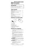
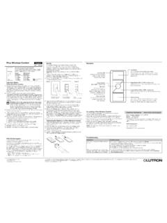
1 Modification instructions for the DuoTherm 900/9000 series furnaces where the thermostat is in the ground side of the circuit for the purpose of adding a Fan control board. Typical wiring schematic for DuoTherm 900/9000. Sail switch Limit switch Thermal fan switch 5 B. Relay Standard Ignitor board 7 A. FUSE. Battery (+) POWER. NC. VALVE. LED. SENSE. ground . Gas valve Battery (-). Fan Motor M. UIB S. MODEL. thermostat (in the ground circuit). Modified wiring schematic for DuoTherm 900/9000. *Note: This modification should be done by trained service technicians This schematic shows how to wire the thermostat from the ground side of the circuit to the positive side of the circuit so that a Fan control board can be installed. These drawings are provided as a courtesy and are to be used at your own discretion. Modification of any gas appliance can void manufacture warranties and/or cause serious injury or fatalities. We recommend that these modifications be done by a qualified service technician familiar with RV gas appliances.
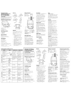
2 thermostat (in the Battery + circuit). Sail switch Limit switch Thermal fan switch 5 B. Relay Standard Ignitor board 7 A. FUSE. Battery (+) POWER. NC. VALVE. LED. SENSE. ground . Gas valve Battery (-). Fan Motor M. UIB S. MODEL. Page 1. Wiring schematic for installing a Dinosaur Fan control board or Fan 50 Plus board in a DuoTherm 900/9000 furnace thermostat (in the Battery + circuit). Sail switch Limit switch Fan switch 5 B Dinosaur FAN control board or FAN 50 Plus Relay board 7 A. FUSE. Battery (+) POWER. NC. VALVE. LED. SENSE. ground . Gas valve Battery (-). Fan Motor M. FAN 50 plus MODEL. BLOWER PWR. RED WIRE (POWER). ORANGE WIRE (BLOWER). Page 2.


![3 b ], B D q 3 b.I ], A q C Typical Boost Settings For ...](/cache/preview/a/3/e/6/a/2/8/d/thumb-a3e6a28de41c190078e312ca74651b92.jpg)
