Transcription of DR series manual - cpicomm.com
1 Instruction manual DR series DC Remote Controls 1/2013. CPI Communications 941 Hensley Lane Wylie, Texas 75098. Phone (972)429-7160 (800)869-9128 Fax (972)429-7165 (888) 437-5360 SPECIFICATIONS Subject to change without notice. Power Requirements 120 VAC, 60 Hz for wall pack (provided) operation 12 VDC to 16 VDC @ 600 mA maximum. Fused on circuit board. Dimensions 9" x 4" x 7" inches Weight DR10 - 5 lbs, DR20 - 5 lbs, DR30 - 5 lbs, DR40 - 5 lbs. audio Output to Speaker 2 Watts at 3% THD into 8 ohms, using supplied wall pack or 12 VDC. Handset Earpiece Level Adjustable via internal potentiometer. Frequency Response +/- 3dB from 300 to 3000 Hz. 1000 Hz reference. Hum and Noise 50 dB below operating levels Compression Less than 3 dB increase in output with 30 dB increase in input beyond threshold. Threshold is adjustable from -20 dBm to +10 dBm.
2 Line Impedance 600 ohms or 5000 ohms, dip switch selectable. Line Output Level Factory set at 0 dBm. Adjustable to +15 dBm maximum. Control Currents Dip switch selection of eight possible control current configurations com- posed of the following current levels: -15mA, -6mA, , + , +6mA. and +15mA. Operating Modes Standard: Two wire simplex. Two wire duplex. (Trunking mode, jumper selectable.). Optional: -4W Four wire simplex. audio on one pair and control currents on the other. -FD Full duplex on four wires. TX audio and control currents on one pair, RX audio on the second pair. Available Factory Options -M Push button monitor. -2F F1 / F2 push button. Current format is dip switch selectable. -I Push button intercom between remotes. Please note: Some options are standard on some models. Some options not available on all models or in combinations with other options.
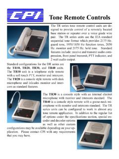
3 No options are field installable. General Description The DR series DC remotes are designed to provide remote control of a conventional or trunked two way radio base station or repeater via a leased wire line or in-house twisted pair. The DR series is available in four different housing configurations. They are: the DR10 telephone style unit with handset, the DR20 desktop console with desk microphone, the DR30 desktop console with built in electret condenser microphone and the DR40 desktop console with goose neck microphone. Standard features on all DR models include front panel PTT switch, line operated transmit indicator, off-hook monitor function(DR10), RX and TX audio compression, two watt amplified speaker with volume control, line continuity sensor and parallel cross mute capability. The DR10, 20, 30 and 40 may be wall mounted by ordering the -WM option.
4 When wall mounting the DR20. please note, no provisions are made for mounting the desk microphone. 2. Pre-Installation Considerations The DR series DC remotes are designed with protection against both power and telephone line surges. This protection circuitry requires the use of a properly grounded AC outlet. If the remote is to be powered directly from DC the wall plug-in transformer is not used Phone lines The DR series is designed to work with a good quality leased metallic pair (phone line) or in house twisted pair wiring. The maximum dc loop resistance, including the termination panel, cannot be greater than 10,000 ohms. Parallel operation When several remote control units are connected in parallel the total system impedance will decrease to a point where operation is degraded. To compensate for this effect, DR series remotes provide a dip-switch selectable 600 or 5000 ohm termination impedance.
5 In parallel remote installations using the same phone line, dip switch 7 should be in the OFF position (5000. ohms), in all remotes except the last one in the chain. For multi-point installations using more than one phone line the above procedure applies to each phone line. Up to ten DR series DC remotes may be connected in parallel. The maximum loss between any remote and the termination panel must not exceed 20dB. Installation Connections Phone line connections are made using the supplied modular line cord. Power consist of plugging the wall pack in to the nearest properly grounded AC outlet. If the remote is to be powered directly from a DC source, disconnect the wall plug-in transformer from TB1 and connect a well grounded 12 to 16 volt DC supply. The positive lead should connect to TB1 pin 1. The negative lead should connect to TB1 pin 2.
6 Control Current Settings - Table 1 shows the eight possible control current combinations available in the DR. series remote. Switches 1, 2 and 3 of the dip switch are used to select the desired control current format. They are accessible on the underside of the remote. Table 1. PTT (F1) PTT (F2) Mon (F1) Mon (F2) Switch 1 Switch 2 Switch 3. +15mA OFF OFF OFF. +6mA ON OFF OFF. +15mA +6mA OFF ON OFF. +15mA -6mA ON ON OFF. +6mA + OFF OFF ON. +6mA ON OFF ON. +6mA +15mA OFF ON ON. +15mA -15mA +6mA -6mA ON ON ON. Field Selectable Configuration Settings The DR series remotes are designed to be as user / technician friendly as possible and provide a wide range of field selectable options. These dip switch selectable and jumper selectable options give the DR series great flexibility in the field. Table 2 illustrates the field configuration settings that are dip switch selectable.
7 3. Table 2. Switch # ON OFF. 4 Phone line polarity is reversed. Phone line polarity normal. 5 Speaker volume can be turned all the way Speaker volume can not be turned all the down. way down. 6 Speaker active on-hook. Speaker active all the time. 7 600 ohm termination. 5000 ohm termination. 8 DR10 DR20. Jumper Settings The DR series DC remotes have 21 solder dot jumpers on the PCB. Jumpers are considered to be "in" when solder has been applied to form a short from one side to the other. Jumpers are considered to be "out" when no solder has been applied and the circuit is open from one side to the other. Remove the four housing screws and open housing to access jumpers. The following describes field selectable jumper functions. JU19 - Off-hook monitor function. Generates monitor current when handset is off-hook. IN = disabled, OUT = enabled. Must be IN for DR20, DR30 and DR40.
8 JU20 - Parallel Transmit Indication (PTI). Energizes PTT indicator when a parallel remote keys, locks out TX audio and disables control current generation from this remote. IN = disabled, OUT = enabled. See "Setup Adjustments" for adjustment procedure. JU16 - Cross Mute. Mutes speaker when a parallel remote keys. IN = enabled, OUT = disabled. Requires PTI enabled and adjusted. JU14 - Trunking option for 2 wire system. Allows trunking status tones to be heard in earpiece while remote is keyed. IN = disabled, OUT = enabled. Can not be used for DR20, DR30 or DR40 in 2 wire system. JU17 & JU18 - High Loop Resistance. Allows use of PTI on DC loops with 6K to 10K resistance. IN = Loop resistance is 6K to 10K. OUT = Loop resistance is less than 6K. Ignore if PTI not enabled. A description of all jumper functions appears on the schematic next to the jumper.
9 Line Continuity Sense This feature will tell you, via the PTT LED, if your DC loop continuity has been lost. If the unit is keyed and there is no DC loop continuity, the PTT LED will not illuminate. When the unit is un- keyed, the PTT LED will flash once. There are no adjustments for this feature. Setup Adjustments The following adjustments assume that the termination panel has been properly installed. 4. Receive Line Input Adjustment The receive line input, R92, adjusts the audio level to the input of the compression amplifier circuitry. This allows the threshold of compression be adjusted from -20 dBm to +10 dBm. While applying an RF signal modulated with a 1000 Hz tone at 60% system deviation to base station receiver, adjust the termination panel line output control for 0 dBm to the phone line. Adjust each remote as follows: a. Connect a scope or analog AC volt meter to ground and pin 14 of U8.
10 B. With R92 fully counter clockwise, adjust in a clockwise direction until the AC voltage level on scope or meter just stops increasing. This point is the threshold of compression. c. Remove the RF Signal from the base station. Transmit Line Out Adjustment This level is preset at the factory for 0 dBm out to the phone line and should not require readjustment at installation. If needed, the procedure is as follows: 1. With the handset off-hook (if applicable) depress the PTT switch and adjust the mod out pot (R63), while speaking in a normal voice, until 0 dBm is measured across the phone line at the termination panel. Microphone Sensitivity R64 controls the microphone audio level into the transmit compression circuit and therefore acts as a sensitivity control. This potentiometer has been factory set to provide adequate compression for normal voice audio with a relatively quiet background noise level.