Transcription of Patriot Braking System - Blue Ox
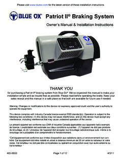
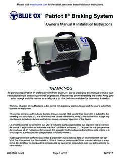
1 Patriot Braking System Owner's Manual & Installation Instructions BRK2012. Patent Pending THANK YOU. for purchasing a Patriot Braking System from Blue Ox . We've organized this manual to make your . installation simple and as trouble-free as possible. Please read before operating the brake. Keep your sales receipt and this manual in a safe place so that both are available for future use if needed. 405-0260 Rev A Page 1 of 12 2/4/14 Patriot Braking System Welcome to the Blue Ox Experience Congratulations! You are now the proud owner of a Patriot Braking System . Welcome to the Blue Ox Family. The Braking System that you have purchased combines quality components with the latest in technology and style. We are confident that these design features will provide you with the conveniences you expect during your travels. After you understand how to properly and safely operate and care for your Patriot , expect years of trouble-free operation and service backed by a two year limited warranty.
2 Please read all of the technical documents, warnings, cautions, tips, and notes in this manual before attempting to operate your Patriot for the first time. Improper installation, use or maintenance may result in malfunction causing personal injury or property damage. Please fill out and return your warranty card or register via our web site at within ten days of delivery. For future reference, your serial number is located on the outside of the manual packaging and is also located on the bottom of your Patriot unit. Equipment Information Record Customer Name: _____. Date Purchased: _____. Purchased From: _____. Address: _____. City:_____ State: ___ Zip Code: _____. Phone Number of Dealership: _____. Installed By: _____. Service #: _____. Model #: _____. Serial #: _____. Notes: _____. _____. ! WARNING ! WARNING. Fully understand these instructions before Always follow the towing procedures in your installing. Improper installation and/or operation vehicle's owners manual.
3 Can create a hazard which can cause serious Do NOT modify your Patriot in any way NOT. injury, property damage or death. Improper authorized by Blue Ox , as it will void the installation and/or operation will void the warranty. warranty. DEALERS AND DISTRIBUTORS: PLEASE give these instructions to the customer so they fully understand the set-up, operation, and safety precautions of this Braking System . 405-0260 Rev A Page 2 of 12 2/14/14 Patriot Braking System Unpacking your Patriot . Remove the Patriot and accessories from the shipping carton, review parts list and diagram below. Make sure that you have the appropriate items shown below. If NOT, please contact a Blue Ox Dealer or Distributor, or call a member of the Customer Care Team at (402) 385-3051 to order replacement parts. Contents: 1. Patriot Unit 2. 2-Way RF In-Coach Controller 3. Brake Feet 4. Breakaway Switch 1 5. Breakaway Lanyard 6. Breakaway Cable 4. 2. 6. 3. 5. Important: USE ONLY GENUINE FACTORY REPLACEMENT PARTS.
4 Do NOT substitute homemade or non-typical parts. This may cause your brake to fail and result in injury or death. If repair parts or components are needed, you may order them through your nearest Blue Ox Dealer or Distributor, or call our Customer Care Team at (402) 385-3051. Safety & Compliance This equipment has been tested and found to comply with the limits for a Class B digital device, pursuant to part 15 of the FCC Rules. These limits are designed to provide reasonable protection against harmful interference in a residential installation. This equipment generates, uses and can radiate radio frequency energy, and if not installed and used in accordance with the instructions, may cause harmful interference to radio communications. However, there is no guarantee that interference will not occur in a particular installation. If this equipment does cause harmful interference to radio or television reception, which can be determined by turning the equipment off and on, the user is encouraged to try to correct the interference by one or more of the following measures: Reorient or relocate the receiving antenna.
5 Increase the separation between the equipment and receiver. Connect the equipment into an outlet on a circuit different from that to which the receiver is connected. Consult the dealer or an experienced radio/TV technician for help To satisfy FCC RF exposure requirements for mobile and base station transmission devices, a separation distance of 20 cm or more should be maintained between the antenna of this device and persons during operation. To ensure compliance, operation at closer than this distance is not recommended. The antenna(s) used for this transmitter must not be co-located or operating in conjunction with any other antenna or transmitter. 405-0260 Rev A Page 3 of 12 2/14/14 Patriot Braking System Jog Switch Carrying Handle Information Display One-button Set-up Actuator Arm Brake Claw Adjustable Push Pad Plug-In Port On/Off Switch 12 Volt Receptacle (2 Amp Max). Patriot Brake Unit RF Remote Unit Manual Override 405-0260 Rev A Page 4 of 12 2/14/14 Patriot Braking System Initial Set-Up In Towed Vehicle 1.
6 Open the driver side door of the towed vehicle and push the driver seat back as far as possible. 2. Place the Patriot unit on the floor. 3. Open the brake claw and place it on the brake pedal. (Figure 1). Reference page 6 for claw operating instructions 4. The feet can be attached and adjusted for proper height position for uneven floorboards. Figure 1. Note: Do not store or transport with the feet attached to the unit. 5. Slide the driver seat forward against the push pads. Adjust the push pad up or down for proper height position in relationship to the seat. Note: Seat must be as far forward as possible without causing the brake lights to be activated. If the seat can't be moved forward far enough, an arm extension is available. 6. Plug in the power cord into a 12 volt power source. The indicator light will glow. 7. Turn on the power switch. (Figure 2) The display will read INITIALIZING . Figure 2. Note: If using a breakaway, it must be connected first prior to turning on power to the unit.
7 8. Push the SET-UP button. (Figure 3) The brake will stroke three (3) times then remain in the ready position. Note: If the brake extends fully and remains extended without stroking three times, the seat is not far enough forward. Turn the brake off then back on. Reposition the seat as far forward as possible without causing the brake lights to be activated then restart set-up process. Figure 3. In the Motor Coach Find a sturdy, easy-to-reach location to mount the RF in-coach controller. The dashboard is the suggested mounting point, but anywhere that is secure and accessible to the driver will work. Using the Velcro provided, attach one side to the desired mount- ing point, and the other side to the controller. Note: The Patriot Brake can be used with or without the RF. controller. We recommend using the controller for the operational feedback, but the brake can be set without the RF controller. Figure 4. 405-0260 Rev A Page 5 of 12 2/14/14 Patriot Braking System Locking Brake Claw Operating Instructions To Open: 1.
8 Place your thumb on top of the claw and place your pointer finger under the back ledge (right). Pinch your fingers together until the claw locks in place (left). To Close: 2. Position the claw onto the brake pedal. NOTE: You can adjust the size of the claw by changing where the top fangs are mounted. 3. Press the button on top of the claw to close the claw or push the front button against the brake pedal. Caution: Make sure your fingers are not between the upper and lower half of the claw when you press the button. To Lock: 4. If the claw is open, you can turn the knob one quarter turn to the left to lock it open. If the claw is closed, you can turn the knob one quarter turn to the left to prevent it from locking open. If the claw is locked, turn the knob one quarter turn to the right to unlock it. 405-0260 Rev A Page 6 of 12 2/14/14 Patriot Braking System Installation Notes When installing the Patriot on hybrids/vehicles with continuous power assist brakes or if the user gets the REPOSITION BRAKE error twice in a row while trying to set-up their brake, then they should do the following: 1.
9 With the brake plugged in but powered off, hold down the SET-UP button while powering on the unit. Once it lights up you can release the set-up button. 2. Once it is finished initializing, the screen will read MODE: FORCE . Hit the JOG switch to the left so that the screen now reads MODE: POSITION . Press SET-UP to select this setting. 3. The next screen will read, MAX FORCE . Press SET-UP again at this screen. 4. The brake should read SETTINGS SAVED! and automatically restart. These setting will be stored in the memory and remain until a user goes through this procedure again and changes them. With these settings, the brake will work on ANY vehicle. For a traditional vehicle, the GAIN setting should be kept between settings 5 and 9. In a hybrid vehicle, the GAIN setting should be kept between settings 1 and 3. Operating Instructions 1. Plug the 2-Way RF In-Coach Controller into an available 12 volt outlet. 2. The large number on the display represents the sensitivity setting of the Patriot Brake; it will automatically be set to 5 when activated.
10 3. Turn the GAIN knob to the left or right to adjust this setting. The lowest setting (0) puts the tow brake on stand-by and will apply no pressure to the brake (except in a breakaway). Settings 1 through 9 will incrementally increase the pressure applied. 4. On the bottom of the RF Controller there is a MANUAL OVERRIDE lever. Pressing down on this lever will cause the Patriot to press down on the brake pedal. Note: This is a progressive lever; the lever controls the Braking according to the level set on the RF controller. This acts like a trailer brake and is useful in wet weather to keep the towed vehicle in line. 5. If the error light turns on, check the display screen on the Patriot unit and refer to the list of possible display messages for assistance. After addressing the problem, turn off the Patriot and restart the set-up procedure. 6. If a breakaway switch is installed and plugged in, the BK / AWAY ON LED should be on. Follow the instructions provided.