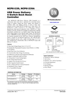
Transcription of SGM6132 3A, 28.5V, 1.4MHz Step-Down Converter
1 SGM6132 3A, , Step-Down Converter SG Micro Corp J U LY2015 R E GENERAL DESCRIPTION The SGM6132 is a current-mode Step-Down regulator with an internal power MOSFET. This device achieves 3A continuous output current over a wide input supply range from to with excellent load and line regulations. The switching frequency of SGM6132 is and current mode operation provides fast transient response and eases loop stabilization. The SGM6132 is highly efficient with peak efficiency at 91% when in operation. In shutdown mode the regulator draws less than 18 A of supply current. Protection features include cycle-by-cycle current limit and thermal shutdown. The device also includes an internal soft-start and an external adjustable soft-start function to limit the inrush current and prevent the overshoot of output voltage.
2 The SGM6132 is available in Green SOIC-8 (Exposed Pad) package and requires a minimum number of readily available external components to complete a 3A Step-Down DC/DC Converter solution. FEATURES 3A Output Current High Efficiency: Up to 91% to Input Voltage Range < 18 A Shutdown Supply Current 100m Internal Power MOSFET switch Fixed Switching Frequency Output Adjustable from to 22V Cycle-by-Cycle Current Limit Protection Thermal Shutdown Protection Under-Voltage Lockout Stable with Low ESR Ceramic Capacitors -40 C to +85 C Operating Temperature Range Available in a Green SOIC-8 (Exposed Pad) Package APPLICATIONS Distributed Power Systems Battery Chargers Flat Panel TVs Set-Top Boxes Pre-Regulator for Linear Regulators Cigarette Lighter Powered Devices DVD/PVR Devices TYPICAL APPLICATION to FR310k R133k Fceramic cap recommendedCOUT47 FD1B340AC6 OptionalR410 or shorted Figure 1.
3 Typical Application Circuit Current (A)Effic ienc y (%)VOUT = = = 12V SGM6132 3A, , Step-Down Converter 2 J ULY 2015 SG Micro Corp PACKAGE/ORDERING INFORMATION MODEL PACKAGE DESCRIPTION SPECIFIED TEMPERATURE RANGE ORDERING NUMBER PACKAGE MARKING PACKING OPTION SGM6132 SOIC-8 (Exposed Pad) -40 C to +85 C SGM6132 YPS8G/TR SGM 6132 YPS8 XXXXX Tape and Reel, 2500 MARKING INFORMATION NOTE: XXXXX = Date Code and Vendor Code. Date Code - WeekVendor Code Date Code - YearXXXXX Green (RoHS & HSF): SG Micro Corp defines "Green" to mean Pb-Free (RoHS compatible) and free of halogen substances. If you have additional comments or questions, please contact your SGMICRO representative directly. ABSOLUTE MAXIMUM RATINGS Supply Voltage VIN .. to 31V SW Voltage VSW .. to VIN + boost Voltage VBS .. VSW - to VSW + 6V All Other Pins .. to 6V Package Thermal Resistance SOIC-8 (Exposed Pad), JA.
4 50 C/W Junction Temperature .. +150 C Storage Temperature Range .. -65 C to +150 C Lead Temperature (Soldering, 10s) .. +260 C ESD Susceptibility HBM .. 4000V MM .. 250V RECOMMENDED OPERATING CONDITIONS Input Voltage Range .. to Operating Temperature Range .. -40 C to +85 C OVERSTRESS CAUTION Stresses beyond those listed in Absolute Maximum Ratings may cause permanent damage to the device. Exposure to absolute maximum rating conditions for extended periods may affect reliability. Functional operation of the device at any conditions beyond those indicated in the Recommended Operating Conditions section is not implied. ESD SENSITIVITY CAUTION This integrated circuit can be damaged by ESD if you don t pay attention to ESD protection. SGMICRO recommends that all integrated circuits be handled with appropriate precautions. Failure to observe proper handling and installation procedures can cause damage.
5 ESD damage can range from subtle performance degradation to complete device failure. Precision integrated circuits may be more susceptible to damage because very small parametric changes could cause the device not to meet its published specifications. DISCLAIMER SG Micro Corp reserves the right to make any change in circuit design, or specifications without prior notice. SGM6132 3A, , Step-Down Converter 3 J ULY 2015 SG Micro Corp PIN CONFIGURATION (TOP VIEW) 312 GNDBSSW46875 INFBSSCOMPENGND SOIC-8 (Exposed Pad) PIN DESCRIPTION PIN NAME FUNCTION 1 BS High-side Gate Drive boost Input. BS supplies the driver for the high-side N-Channel MOSFET switch . Connect a 10nF or greater capacitor from SW to BS to power the high-side switch . A 10 resistor placed between SW and BS cap is strongly recommended to reduce SW spike voltage.
6 2 IN Power Input. IN supplies the power to the IC, as well as the Step-Down Converter switches. Drive IN with a to power source. Bypass IN to GND with a sufficiently large capacitor to eliminate noise on the input to the IC. 3 SW Power Switching Output. SW is the switching node that supplies power to the output. Connect the output LC filter from SW to the output load. Note that a capacitor is required from SW to BS to power the high-side switch . 4 GND Ground. (Connect the exposed pad on backside to pin 4.) 5 FB Feedback Input. The voltage at this pin is regulated to Connected to the resistor divider between output and ground to set output voltage. 6 COMP Compensation Node. COMP is used to compensate the regulation control loop. Connect a series RC network from COMP to GND to compensate the regulation control loop. In some cases, an additional capacitor from COMP to GND is required.
7 7 EN Enable Input. EN is a digital input that turns the regulator on or off. Drive EN high to turn on the regulator, and drive EN low to turn it off. Output voltage is discharged when the IC is off. For automatic startup, leave EN unconnected. 8 SS Soft-Start Control Input. SS controls the soft-start period. Connect a capacitor from SS to GND to set the soft-start period. A F capacitor sets the soft-start period to 10ms. To disable the soft-start feature, leave SS unconnected. Exposed Pad GND Power Ground Exposed Pad. Must be connected to GND plane. SGM6132 3A, , Step-Down Converter 4 J ULY 2015 SG Micro Corp ELECTRICAL CHARACTERISTICS (VIN = 12V, TA = +25 C, unless otherwise noted.) PARAMETER SYMBOL CONDITIONS MIN TYP MAX UNITS Input Voltage Range VIN V Feedback Voltage VFB V Shutdown Supply Current ISHDN VEN = 0V 10 18 A Quiescent Supply Current IQ VEN = , VFB = 1V mA High-side switch (M1) On-Resistance RONH 100 m Low-side switch (M2)
8 On-Resistance RONL 10 Error Amplifier Transconductance GEA VFB = 500 800 1120 A/V Error Amplifier Voltage Gain AEA 10000 V/V SW Leakage Current ILSW VEN = 0V, VSW = 0V 1 A Current Limit ILIM A Current Sense to COMP Transconductance GCS A/V Maximum Duty Cycle DMAX VFB = 80 % Minimum Duty Cycle DMIN VFB = 1V 0 % EN Threshold Voltage VIH V EN Threshold Voltage VIL V EN Pull-Up Current VEN = 0V 2 A Oscillator Frequency fOSC MHz Short-Circuit Oscillator Frequency VFB = 0V 140 kHz Under-Voltage Lockout Threshold VIN Rising V Under-Voltage Lockout Threshold Hysteresis 230 mV Soft-Start Period CSS = F 10 ms Thermal Shutdown Temperature TSHDN 160 C SGM6132 3A, , Step-Down Converter 5 J ULY 2015 SG Micro Corp TYPICAL PERFORMANCE CHARACTERISTICS VIN = 12V, CIN = 22 F, COUT = 47 F, L = H and TA = +25 C, unless otherwise noted.
9 Feedback Voltage vs. Temperature Efficiency vs. Load Current Steady State Operation Steady State Operation Shutdown Through Enable Shutdown Through Enable Voltage (V) Temperature ( C) (%) Load Current (A) VIN = 24V VOUT = VOUT = SGM6132 3A, , Step-Down Converter 6 J ULY 2015 SG Micro Corp TYPICAL PERFORMANCE CHARACTERISTICS (continued) VIN = 12V, CIN = 22 F, COUT = 47 F, L = H and TA = +25 C, unless otherwise noted. Startup Through Enable Startup Through Enable Startup Through Enable Startup Through Enable Load Transient Response SGM6132 3A, , Step-Down Converter 7 J ULY 2015 SG Micro Corp OPERATION Main Control Loop The SGM6132 is a current-mode Step-Down regulator. It regulates input voltages from to down to an output voltage as low as , and is able to supply up to 3A of load current.
10 The SGM6132 uses current-mode control to regulate the output voltage. The output voltage is measured at FB through a resistive voltage divider and amplified through the internal error amplifier. The output current of the transconductance error amplifier is presented at COMP where a network compensates the regulation control system. The voltage at COMP is compared to the switch current measured internally to control the output voltage. The Converter uses an internal N-Channel MOSFET switch to Step-Down the input voltage to the regulated output voltage. A boost capacitor connected between SW and BS drives the gate of MOSFET, and makes it greater than input voltage while SW is high. Thus, the MOSFET will be in low resistance conducting state. The capacitor is internally charged while SW is low.