Transcription of Chapter 4a – Development of Beam Equations
1 Chapter 4a Development of beam Equations Learning Objectives To review the basic concepts of beam bending To derive the stiffness matrix for a beam element To demonstrate beam analysis using the direct stiffnessmethod To illustrate the effects of shear deformation in shorterbeams To introduce the work-equivalence method for replacingdistributed loading by a set of discrete loads To introduce the general formulation for solving beamproblems with distributed loading acting on them To analyze beams with distributed loading acting onthemChapter 4a Development of beam Equations Learning Objectives To compare the finite element solution to an exactsolution for a beam To derive the stiffness matrix for the beam element withnodal hinge To show how the potential energy method can be usedto derive the beam element Equations To apply Galerkin s residual method for deriving thebeam element equationsCIVL 7/8117 Chapter 4 - Development of beam Equations - Part 11/39 Development of beam EquationsIn this section, we will develop the stiffness matrix for a beam element, the most common of all structural elements.
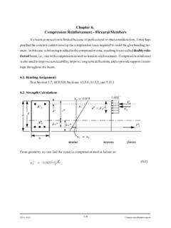
2 The beamelement is considered to be straight and to have constant cross-sectional area. Development of beam EquationsWe will derive the beam element stiffness matrix by using the principles of simple beam theory. The degrees of freedom associated with a node of a beam element are a transverse displacement and a rotation. CIVL 7/8117 Chapter 4 - Development of beam Equations - Part 12/39 Development of beam EquationsWe will discuss procedures for handling distributed loading and concentrated nodal will include the nodal shear forces and bending moments and the resulting shear force and bending moment diagrams as part of the total of beam EquationsWe will develop the beam bending element Equations using the potential energy approach. Finally, the Galerkin residual method is applied to derive the beam element Equations CIVL 7/8117 Chapter 4 - Development of beam Equations - Part 13/39 beam StiffnessConsider the beam element shown below.
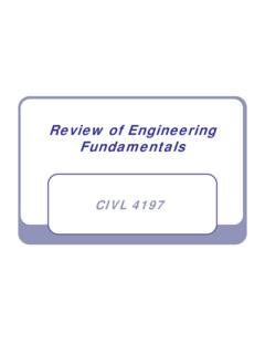
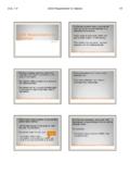
3 The beam is of length Lwith axial local coordinate xand transverse local coordinate y. The local transverse nodal displacements are given by viand the rotations by i. The local nodal forces are given by fiyand the bending moments by mi. positive in the positive ydirection. beam StiffnessAt all nodes, the following sign conventions are used on the element positive in the counterclockwise direction. positive in the counterclockwise direction. positive in the positive y direction. CIVL 7/8117 Chapter 4 - Development of beam Equations - Part 14/39At all nodes, the following sign conventions are used on the global level:1. Bending momentsmare positive if they cause the beam to bend concave up. 2. Shear forces Vare positive is the cause the beam to rotate clockwise. beam StiffnessBeam Stiffness(+) Bending Moment(-) Bending MomentCIVL 7/8117 Chapter 4 - Development of beam Equations - Part 15/39 beam Stiffness(+) Shear Force(-) Shear ForceBeam StiffnessThe differential equation governing simple linear-elastic beam behavior can be derived as follows.
4 Consider the beam shown 7/8117 Chapter 4 - Development of beam Equations - Part 16/39 beam StiffnessThe differential equation governing simple linear-elastic beam behavior can be derived as follows. Consider the beam shown the Equations of equilibrium for the differential element:0right sideM 0yF ()wxdx2dx ()2dxMMdMVdxwxdx ()()VVdVwxdx 0 beam StiffnessFrom force and moment equilibrium of a differential beam element, we get:00right sideMVdx dM 00yFwdx dV ddMwdx dx ordMVdx ordVwdx CIVL 7/8117 Chapter 4 - Development of beam Equations - Part 17/39 beam StiffnessThe curvature of the beam is related to the moment by:1 MEI where is the radius of the deflected curve, vis the transverse displacement function in the ydirection, Eis the modulus of elasticity, and Iis the principle moment of inertia about ydirection, as shown StiffnessThe curvature, for small slopes is given as:dvdx 22dvdx Therefore:2222dv MdvMEIdxEIdx Substituting the moment expression into the moment-load Equations gives.
5 2222ddvEIw xdxdx For constant values of EI, the above equation reduces to: 44dvEIw xdx CIVL 7/8117 Chapter 4 - Development of beam Equations - Part 18/39 beam StiffnessStep 1 - Select Element TypeWe will consider the linear-elastic beam element shown below. beam StiffnessStep 2 - Select a Displacement FunctionAssume the transverse displacement function vis:321234vaxaxaxa The number of coefficients in the displacement function aiis equal to the total number of degrees of freedom associated with the element (displacement and rotation at each node). The boundary conditions are:1(0)vxv 10xdvdx 2xLdvdx 2()vx L v CIVL 7/8117 Chapter 4 - Development of beam Equations - Part 19/39 beam StiffnessStep 2 - Select a Displacement FunctionApplying the boundary conditions and solving for the unknown coefficients gives:Solving these Equations for a1, a2, a3,and a4gives:14(0)vva 3221 2 3 4()vL v aL aL aL a 13(0)dvadx 221 23()32dv LaLa L adx 312123221vvvxLL 212121 12312vvx xvLL beam StiffnessStep 2 - Select a Displacement FunctionIn matrix form the above Equations are.
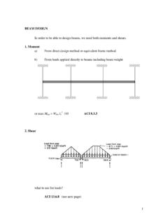
6 Where []vNd 11123422[]vdNNNNNv 3233 223123311232 NxxL LNxLxL xLLL 3232234331123 NxxLNxLxLLL CIVL 7/8117 Chapter 4 - Development of beam Equations - Part 110/39 beam StiffnessStep 2 - Select a Displacement FunctionN1, N2, N3, and N4are called the interpolation functionsfor a beam StiffnessStep 3 - Define the Strain/Displacement and Stress/Strain RelationshipsThe stress-displacement relationship is:We can relate the axial displacement to the transverse displacement by considering the beam element shown below:where uis the axial displacement function. ,xduxydx CIVL 7/8117 Chapter 4 - Development of beam Equations - Part 111/39 beam StiffnessStep 3 - Define the Strain/Displacement and Stress/Strain Relationshipsdvuydx beam StiffnessStep 3 - Define the Strain/Displacement and Stress/Strain RelationshipsOne of the basic assumptions in simple beam theory is that planes remain planar after deformation, therefore:Moments and shears are related to the transverse displacement as: ,xduxydx 22dvmx EIdx 33dvVx EIdx 22dvydx CIVL 7/8117 Chapter 4 - Development of beam Equations - Part 112/39 beam StiffnessStep 4 - Derive the Element Stiffness Matrix and EquationsUse beam theory sign convention for shear force and bending +V+M+M+ beam StiffnessStep 4 - Derive the Element Stiffness Matrix and EquationsUsing beam theory sign convention for shear force and bending moment we obtain the following Equations .
7 31112233012 6 12 6yxdvEIfVEIv L v LdxL 3211223312 6 12 6yxLdvEIfVEIvL vLdxL 222111222306462xdvEImmEILvL LvLdxL 22221122236264xLdvEImmEILv L Lv LdxL CIVL 7/8117 Chapter 4 - Development of beam Equations - Part 113/39 beam StiffnessStep 4 - Derive the Element Stiffness Matrix and EquationsIn matrix form the above Equations are:112211322222212 6 12 664 6212 6 12 662 64yyfvLLmLL LLEIfvLLLmLL LL where the stiffness matrix is:2232212 6 12 664 6212 6 12 662 64 LLLL LLEILLLLL LL k11112222yyfvmkfvm beam StiffnessStep 4 - Derive the Element Stiffness Matrix and EquationsBeam stiffness based on Timoshenko beam TheoryThe total deflection of the beam at a point xconsists of two parts, one caused by bending and one by shear force. The slope of the deflected curve at a point xis: dvxxdx CIVL 7/8117 Chapter 4 - Development of beam Equations - Part 114/39 beam StiffnessStep 4 - Derive the Element Stiffness Matrix and EquationsBeam stiffness based on Timoshenko beam TheoryThe relationship between bending moment and bending deformation is: dxMx EIdx beam StiffnessStep 4 - Derive the Element Stiffness Matrix and EquationsBeam stiffness based on Timoshenko beam TheoryThe relationship between shear force and shear deformation is: sVx kAG x where ksAis the shear area.
8 CIVL 7/8117 Chapter 4 - Development of beam Equations - Part 115/39 beam StiffnessStep 4 - Derive the Element Stiffness Matrix and EquationsBeam stiffness based on Timoshenko beam TheoryYou can review the details in your book, but by including the effects of shear deformations into the relationship between forces and nodal displacements a modified elemental stiffness can be developed. beam StiffnessStep 4 - Derive the Element Stiffness Matrix and EquationsBeam stiffness based on Timoshenko beam Theory 22322661212426666112122466 LLLLLLEILLLLLLL k212sEIkAGL CIVL 7/8117 Chapter 4 - Development of beam Equations - Part 116/39 beam StiffnessStep 5 - Assemble the Element Equations and Introduce Boundary ConditionsConsider a beam modeled by two beam elements (do not include shear deformations):Assume the EIto be constant throughout the beam . A force of 1,000 lband moment of 1,000 lb-ft are applied to the mid-point of the beam .
9 beam StiffnessStep 5 - Assemble the Element Equations and Introduce Boundary ConditionsThe beam element stiffness matrices are:11 2 222(1)32212 6 12 664 6212 6 12 662 64vvLLLL LLEILLLLL LL k22 3 322(2)32212 6 12 664 6212 6 12 662 64vvLLLL LLEILLLLL LL kCIVL 7/8117 Chapter 4 - Development of beam Equations - Part 117/39112211223222 22233223312 61260 064 6 2 0012 6 12 12 6 6 12 662 6644 6200 12 6 12600 6 2 64yyyFvLLMLLLLFvLLLLEIMLLL LLLL LLFvLLLLLLM beam StiffnessStep 5 - Assemble the Element Equations and Introduce Boundary ConditionsIn this example, the local coordinates coincide with the global coordinates of the whole beam (therefore there is no transformation required for this problem). The total stiffness matrix can be assembled as:Element 1 Element 2 beam StiffnessStep 5 - Assemble the Element Equations and Introduce Boundary ConditionsThe boundary conditions are:11 30vv 112211223222 22233223312 61260 064 6 2 0012 6 12 12 6 6 12 66 2 664 4 6200 12 6 12600 6 2 64yyyFvLLMLLLLFvLLLLEIMLLL LLLL LLFvLLLLLLM 223000v CIVL 7/8117 Chapter 4 - Development of beam Equations - Part 118/39 beam StiffnessStep 5 - Assemble the Element Equations and Introduce Boundary ConditionsBy applying the boundary conditions the beam Equations reduce to:222232231, 0 0 02 4 0 61,0000 8 20624lbLvEIlb ftLLLLL L beam StiffnessStep 6 - Solve for the Unknown Degrees of FreedomSolving the above Equations gives.
10 22 33222875 375125 625125 125124 LLLLLL vinradradEIEIEI Step 7 - Solve for the Element Strains and Stresses 22dvmx EIdx 121222vdNEIvdx The second derivative of Nis linear; therefore m(x) is 7/8117 Chapter 4 - Development of beam Equations - Part 119/39 beam StiffnessStep 6 - Solve for the Unknown Degrees of FreedomSolving the above Equations gives:22 33222875 375125 625125 125124 LLLLLL vinradradEIEIEI Step 7 - Solve for the Element Strains and Stresses 33dvVx EIdx 131222vdNEIvdx The third derivative of Nis a constant; therefore V(x) is Stiffness 22dvmx EIdx 121222vdNEIvdx Step 7 - Solve for the Element Strains and Stresses 221112236462 EImLvLLvLL 222112236264 EImLvLLvLL Assume L= 120 in, E= 29x106psi, and I= 100 in4:Element #1:3,875lb ft 3, ft 10vinradrad CIVL 7/8117 Chapter 4 - Development of beam Equations - Part 120/39 beam Stiffness 22dvmx EIdx 121222vdNEIvdx Step 7 - Solve for the Element Strains and Stresses 222223336462 EImLvLLvLL 223223336264 EImLvLLvLL Assume L= 120 in, E= 29x106psi, and I= 100 in4:Element #2:2, ft 0 10vinradrad beam StiffnessStep 7 - Solve for the Element Strains and StressesAssume L= 120 in, E= 29x106psi, and I= 100 in4.