Transcription of Digital voltage regulator - Nidec Leroy-Somer
1 D350 Digital voltage regulatorInstallation and maintenanceElectric Power GenerationInstallation and maintenanceDigital voltage regulator D350 SAFETY MEASURESB efore using your machine for the first time, it is important to read the whole of this installation and maintenance necessary operations and interventions on this machine must be performed by a qualified technical support service will be pleased to provide any additional information you may various operations described in this manual are accompanied by recommendations or symbols to alert the user to potential risks of accidents. It is vital that you understand and take notice of the fol-lowing warning symbol for an operation capable of damaging or destroying the machine or surrounding equipment.
2 Warning symbol for general danger to personnel. Warning symbol for electrical danger to servicing or repair operations performed on the AVR should be undertaken by personnel trained in the commissioning, servicing and maintenance of electrical and mechanical com-ponents. When the generator is driven at a frequency below 28 Hz for more than 30 seconds with an analogue AVR, its AC power supply must be disconnected. WARNINGThis AVR can be incorporated in a EC-marked manual is to be given to the end user. - We reserve the right to modify the characteristics of this product at any time in order to incorporate the latest technological developments. The information contained in this document may therefore be changed without document may not be reproduced in any form without prior brands and models have been registered and patents applied manual concerns the alternator AVR which you have just wish to draw your attention to the contents of this maintenance en - / eElectric Power Generation Installation and maintenance 5611 en - / e Digital voltage regulator D350 3 Table of content 1.
3 General Instructions .. 5 Identity sheet .. 5 General Presentation .. 5 The D350 AVR .. 5 NFLink configuration module .. 6 Technical characteristics .. 7 D350 AVR Dimensions .. 9 D350 AVR and NFLink Dimensions .. 10 Mounting .. 11 Wiring .. 11 Alternator voltage measurement: .. 11 Inputs/outputs .. 12 Power supply and excitation .. 14 Alternator current measurement (parallel operation CT): .. 16 Wiring precautions .. 16 2. Operations Instructions .. 18 Description of manual controls and signaling .. 18 The potentiometers .. 18 The LED .. 18 Description of the operating 19 3. Setting instructions .. 21 PC Software .. 21 Software installation .. 21 Different access levels of Easyreg Advanced .. 23 Description of the banner and tabs .. 24 Communication with the D350.
4 26 Configuration window .. 27 Create a new quick configuration .. 30 Step 1: Selection of the alternator type .. 30 Step 2: Definition of the alternator features .. 31 Step 3: Wiring .. 31 Step 4: Regulation mode selection .. 32 Step 5: Configuration upload .. 33 Create a new configuration in custom mode .. 33 Step 1: Description of the alternator .. 34 Step 2: AVR wiring .. 35 Step 3: Definition of the over excitation limit .. 36 Step 4: Definition of stator current monitoring .. 37 Step 5: Definition of the protections .. 37 Step 6a: Setting of the voltage soft start .. 40 Step 6b: voltage regulation .. 41 Step 6c: Regulation of the field current (Manual mode) .. 47 Step 7: Setting the PID gains .. 49 Step 8: Inputs and outputs management .. 50 Step 9: Log Event.
5 51 Step 10: The Second Configuration .. 52 Electric Power Generation Installation and maintenance 5611 en - / e Digital voltage regulator D350 4 Oscilloscope window .. 53 Curves .. 53 Trigger .. 55 Cursors .. 56 Transient test .. 57 Open a curve or an oscilloscope display configuration .. 58 Save a curve or an oscilloscope display configuration .. 58 Change the plotting area background .. 58 Monitor window .. 59 Display units .. 59 Graph .. 60 Gauges .. 60 Change the size of an object .. 61 Delete an object .. 62 Save a monitor configuration .. 62 Open a monitor configuration .. 62 Operations as analogue AVR .. 63 voltage setting .. 63 Stability setting .. 64 Droop compensation .. 64 Switching 50/60Hz .. 64 Tips and tricks .. 65 Comparison window.
6 65 4. APPENDICES .. 67 Vector permutations .. 67 Regulation modes prioritization .. 68 Electrical diagrams .. 69 shunt .. 69 arep .. 70 PMG .. 71 Faults trouble shouting .. 72 No voltage .. 72 voltage too low .. 73 voltage unstable .. 74 Important voltage drop on load .. 75 Time response too long .. 76 Electric Power Generation Installation and maintenance 5611 en - / e Digital voltage regulator D350 5 1. General Instructions Identity sheet The D350 has been manufactured by: MOTEURS Leroy-Somer Boulevard Marcellin Leroy, CS 10015 16915 ANGOULEME Cedex 9, France General Presentation The D350 AVR This manual describes how to install, use, set up and maintain the D350 AVR. The purpose of this AVR is to regulate alternators with a field current of less than 5 A in continuous operations, and 10 A maximum in the event of short-circuit for 10 seconds maximum.
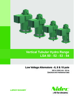
7 Its design is in accordance with mounting in a generator terminal box or a control cabinet. It is required, at a minimum, to follow the local protection and safety standards, especially those specific to electrical installations for voltages of 300 VAC phase-to-neutral maximum. Similarly to the other AVR, the D350 is an electronic printed circuit board, protected with a polyurethane resin as show on the figure below. Description Type Code Digital AVR D350 40035333 Configuration module NFLink 40037656 F2 F1 Fuse references - In standard: F1: 10A 250V ref. Mersen Q206071T or equivalent F2: 10A 250V ref. Mersen Q206071T or equivalent - For UL applications: F1: 8A 250V ref. Mersen T084013T or equivalent F2: 10A 250V ref. Mersen Q206071T or equivalent Electric Power Generation Installation and maintenance 5611 en - / e Digital voltage regulator D350 6 NFLink configuration module The D350 AVR is equipped with NFC1 technology for communication and configuration purposes.
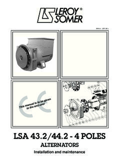
8 The configuration module hereafter called NFLink is placed on the plastic enclosure thanks to two dedicated positioning holes as shown below. NOTE: A holding system placed at the bottom of the NFLink ensures a mechanical strength hold on the D350 plastic board. Once the configuration is done, the NFLink must be removed as it is not supposed to be left on the D350 when it is in continuous operation. 1 Near Field Communication NFLink positioning holes Configuration module NFLink Electric Power Generation Installation and maintenance 5611 en - / e Digital voltage regulator D350 7 Technical characteristics The D350 AVR is a Digital voltage regulator used to control the alternator from the field current or the output voltage regulation loops.
9 voltage regulation: With or without reactive droop compensation droop to allow parallel machine operation. With or without line droop Regulation of the field current, or manual mode, which allows direct control of the field current value. The D350 can also be used to: Adjust the reference for the regulation mode in progress, using an analogue input (0-10V and potentiometer) Monitoring of temperature sensor (Pt100 or CTP) Limit the minimum field current delivered to the exciter field Monitoring of the maximum stator current limit Loss of voltage sensing Withstand a sudden short-circuit for 10 seconds maximum in arep , PMG Signals monitoring (events logger) The various trip, regulation mode and measurement data items can be delivered onto the 2 Digital outputs.
10 Alternator voltage sensing: 3 phases without neutral, 2 phases or 1 phase with neutral Three-phase range0-530 VAC Consumption< 2VA Stator current measurement with CT: Range0-1A ou 0-5A Consumption< 2VA Power supply: AC: 4 terminals for PMG, arep , shunt Range50-277 VAC Consumption max< 3000VA DC (preloading not managed): Range50-400 VDC Consumption max< 3000VA Field excitation Rated0-5 A Short-circuit 10A max. Field winding resistance> 4 ohms Frequency Range10-100Hz 2 The reactive droop and the line droop compensation cannot be simultaneously enabled and a current transformer is required in both cases. Electric Power Generation Installation and maintenance 5611 en - / e Digital voltage regulator D350 8 Regulation accuracy: + of the average of the three phases on a linear load, with harmonic distortion less than 5% voltage adjustment range: 0 to 150% of the rated voltage Quadrature droop adjustment range: -20% to 20% Under frequency protection: integrated, adjustable threshold, slope adjustable from to 3 x V/Hz in steps of V/Hz Excitation ceiling: adjustable by configuration at 3 points Environment: ambient temperature from -40 C to +65 C, relative humidity of less than 95%, non-condensing, mounted in a cabinet or in a terminal box AVR parameters set using software "EasyReg Advanced" provided by Leroy-Somer Dimensions.