Audio Resistor
Found 10 free book(s)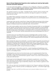
How to Choose Replacement Capacitors and ... - Condor Audio
www.condoraudio.comIn RF circuits, above about 14-18KHz, the impedance of a Metal Film resistor changes - see the attached diagram. So you have to be sure about the resistor value and frequency in RF circuits. In Audio Frequency circuits, generally no problem, because the …

a Audio Preamplifier Self-Contained SSM2019
www.analog.comThe SSM2019 is a latest generation audio preamplifier, combin-ing SSM preamplifier design expertise with advanced processing. The result is excellent audio performance from a monolithic device, requiring only one external gain set resistor or potentiom-eter. The SSM2019 is further enhanced by its unity gain stability.
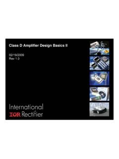
Class D Amplifier Design Basics II - irf.com
www.irf.comGetting Familiar with Class D Audio Amplifier Chapter 2 Latest Class D Audio Amplifier Technology Trend Chapter 3 Identifying Problems ~ Performance Measurement of Class D Amplifier ... Similar to a variable resistor V IN x I IN = V OUT x I OUT Note that input current and output current are not equal. Class AB Class D Bi-directional energy flow ...
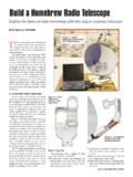
Build a Homebrew Radio Telescope
www.arrl.orga digitally controlled variable resistor. The interface includes a simple Twin-T audio oscillator circuit that provides a tone of approximately 800 Hz that is fed to the com-puter sound card. The amplitude of this audio oscillator is varied by the digital pot that is being controlled by the PIC. The result is the
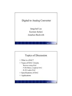
Digital to Analog Converter - gatech.edu
ume.gatech.eduN-Bit Binary Weighted Resistor R/2 LSB + - V out 2 1 4 5 3 1 2 2R 1 2 R V Ref 1 2 8R MSB 1 2 4R ... • Digital Audio • Communications • Countless other applications. 20 References

How to Design 10 kHz filter. (Using Butterworth filter ...
www.egr.msu.eduis set to 9.75 kHz and standard capacitor value for audio circuit design chosen to be 0.01 micro Farads. To calculate Resistor values for High pass filter Equation 2 is used. Where: m = magnitude coefficient f c = 9.75 kHz Cs = 0.01 micro Farads D k = 5 th order normalized capacitor values (Table 2) Table1: Normalized Polynomial table
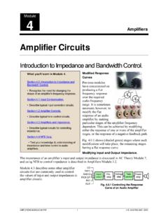
Amplifier Circuits - Learn About Electronics
www.learnabout-electronics.orgThe value of C1 is chosen to pass the higher audio frequencies, this has the effect of progressively reducing the higher frequencies as the variable resistor slider is adjusted towards the bottom end of the tone control, The minimum level of attenuation of the higher (treble) frequencies is limited by R1, which

BASIC ELECTRONIC EXPERIMENTS
pushkin.faculty.unlv.edur 1 134700 470Ω Resistor, 0.25W r 1 141000 1kΩ Resistor, 0.25W r 1 143300 3.3kΩ Resistor, 0.25W r 1 151000 10kΩ Resistor, 0.25W r 1 153300 33kΩ Resistor, 0.25W r 1 161000 100kΩ Resistor, 0.25W r 1 171000 1MΩ Resistor, 0.25W r 1 191549 50kΩ Variable Resistor, lay-down, with dial r 1 235018 0.005μF Disc Capacitor
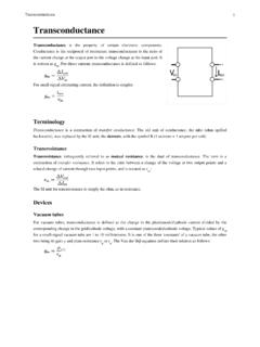
Transconductance - University of Arizona
atlas.physics.arizona.eduA basic inverting transresistance amplifier can be built from an operational amplifier and a single resistor. Simply connect the resistor between the output and the inverting input of the operational amplifier and connect the non-inverting input to ground. The output voltage will then be proportional to the input current at the inverting input,

Technical article - TA0357 - Overview of USB Type-C and ...
www.st.comresistor on the configuration channel (CC) pins. RELATED LINKS 4 USB Type-C and Power Delivery architecture on page 6 5 CC pins: port termination characteristics on page 8 3.2 Sink Port (consumer) This port is able to consume power over V BUS (from 5 V to 20 V and up to 5 A) and must assert a pull-down resistor (Rd) on the CC pins. RELATED LINKS