Boost Converter S
Found 9 free book(s)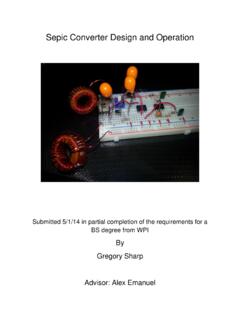
Sepic Converter Design and Operation
web.wpi.eduMay 01, 2014 · boost, Cúk, and SEPIC converters can increase or decrease the voltage. Some applications of converters only need to buck or boost the voltage and can simply use the corresponding converters. However, sometimes the desired output voltage will be in the range of input voltage. When this is the case, it is usually best to use a converter that can

POWER CONVERTER TOPOLOGY TRENDS - PSMA
www.psma.comBOOST BUCK-BOOST BUCK ACTIVE CLAMP 2-SWITCH LLC. Isolated Power Topology Derivatives 8 “Mainstream” Converter Topologies Non-Isolated 1. Boost 4. 2. Buck-Boost 5. 3. Buck 6. Isolated Flyback Forward Push-Pull 7. Half Bridge 8. Full Bridge. Power levels numbers for general . discussion only. Exceptions aplenty.

Introduction to Switch Mode Power Supplies (SMPS)
www.microchip.comThe “Boost” converter is similar to a Buck converter but instead of stepping down the input voltage, the output voltage is higher than the input voltage. The “Buck-Boost” provides a negative output voltage relative to the input voltage. The “Push-Pull” converter is a transformer based converter that is typically
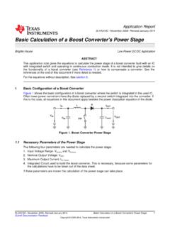
Basic Calculation of a Boost Converter's Power Stage (Rev. C)
www.ti.com4. Integrated Circuit used to build the boost converter. This is necessary, because some parameters for the calculations have to be taken out of the data sheet. If these parameters are known the calculation of the power stage can take place. SLVA372C–November 2009–Revised January 2014 Basic Calculation of a Boost Converter's Power Stage 1

DC-DC Power Converters
ecee.colorado.eduThe first converter is the buck converter, which reduces the dc voltage and has conversion ratio M(D) = D. In a similar topology known as the boost converter, the positions of the switch and inductor are interchanged. This converter produces an output voltage V that is greater in magnitude than the input voltage V g
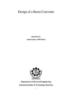
Design of a Boost Converter - nitrkl.ac.in
ethesis.nitrkl.ac.inA boost converter is used as the voltage increase mechanism in the circuit known as the 'Joule thief', which is a circuit topology used with low power battery applications, and is purposed at the ability of a boost converter to 'steal' the remaining energy in a …

Design and Analysis of Buck Converter
www.ijert.orgBoost . 0 . 1 . 1 . 0 . 2 Buck-Boost 0 . 0 . 1 . 1 . 2 Cuk 0 SEPIC . 0 . 1 . 0 . 0 . 1 . C. OPEN LOOP CONTROLLER . The control circuit acts upon the sensed input and output characteristics of the dc-dc converter and ultimately adjusts the duty cycle to allow the converter to respond to system component and load variations. The key component of the

AN-1820LM5032 Interleaved Boost Converter
www.ti.comThe interleaved boost converter design involves the selection of the inductors, the input and output capacitors, the power switches and the output diodes. Both the inductors and diodes should be identical in both channels of an interleaved design. In order to select these components, it is necessary to know the

NCP81239DB - USB Power Delivery 4-Switch Buck Boost …
www.onsemi.com4-Switch Buck Boost Controller The NCP81239 USB Power Delivery (PD) Controller is a ... 28 DBIN The dead battery input to the converter where 5 V is applied. A 1 F capacitor should be placed close to the part to decouple this line. 29 VDRV Internal voltage supply to the driver circuits. A 1 F capacitor should be placed close to the part to decouple