Complex Impedance
Found 9 free book(s)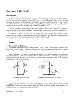
Experiment #1: RC Circuits - Physics Courses
courses.physics.ucsd.edu2.2 Complex Impedance When one is interested in finding the voltage of an element in an AC circuit, the method of complex impedance is very useful. In general, the complex impedance is defined as follows: Z V ~ I ~ (11) where Z is complex (of the form a ib where a & b are real numbers) and V ~ & I ~ are of the form V 0 e
Transmission Line Input Impedance - ITTC
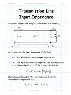
www.ittc.ku.eduimpedance without the complex exponentials: 0 0 0 0 0 0 cos sin cos sin tan tan L in L L L ZjZ ZZ ZjZ ZjZ Z ZjZ β β β β β β ⎛⎞+ = ⎜⎟ ⎝⎠+ ⎛⎞+ = ⎜⎟ ⎝⎠+ AA AA A A Note that depending on the values of 0 β, and Z A, the input impedance can be radically different from the load impedance Z L ! Special Cases Now let’s ...
Introduction to Microstrip Antennas - University of Houston
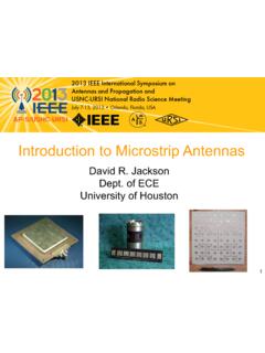
courses.egr.uh.eduintrinsic impedance of free space. η. 1 = intrinsic impedance of substrate. ε. r = relative permtitivity (dielectric consta nt) of substrate. eff. ε. r = effective relative permtitivity (accouting for fringing of flux lines a t edges) eff. ε rc = complex effective relative permtitivity (used in the cavity model to account for all losses)
CHAPTER 8 ANALOG FILTERS
www.analog.comimpedance of capacitors and inductors. Consider a voltage divider where the shunt leg is a reactive impedance. As the frequency is changed, the value of the reactive impedance changes, and the voltage divider ratio changes. This mechanism yields the frequency dependent change in the input/output transfer function that is defined as the frequency

Introduction to RF Filter Design - Rowan University
users.rowan.eduImpedance Transformation • For the Butterworth designs, the source and load resistances have a value of 1. • For the Chebyshev designs, even-number ordered designs have a non-unity load. • Impedance transformation is the process of adjusting all the elements to account for different source and load impedances.

CIRCUITS LABORATORY EXPERIMENT 3 AC Circuit Analysis
classes.engineering.wustl.eduwhere Z is the impedance of the circuit element. The impedance of each of the three linear circuit elements is given as follows: (a) The impedance (ZR) of a resistor is R in rectangular form and R / 0 o in angle form. From Equation (3.7), we see that the phasor voltage at the terminals of a resistor equals R times the phasor current. The phasor ...

Chapter 7: TEM Transmission Lines - MIT OpenCourseWare
ocw.mit.edubehavior, so complex notation is commonly used. Such lines are the subject of this chapter. For broadband signals such as those propagating in computers, complex notation can be awkward and the physics obscure. In this case the signals are often analyzed in the time domain, as introduced in Section 7.1.2 and discussed further in Section 8.1.

RF Power Amplifiers - MIT OpenCourseWare
ocw.mit.eduzDetermine input impedance for each stage zDesign matching networks for inter-stage, load and input REALITY: zI MAX doesn’t scale nicely with transistor size. Without good I MAX numbers, can’t determine R L,opt. Need to do load-pull. zEven load pull measurements have limited accuracy for very large transistors zDesigns are very empirically ...

Pass-Transistor Logic - University of Waterloo
ece.uwaterloo.casignals require extra circuitry, complex gates such as XORs, MUXs and adders can be realized efficiently. • CPL is a static gate, because outputs are connected to Vdd or GND through a low-resistance path (high noise resilience). • Design is modular – all gates use same topology; only inputs are permuted. This fac ilitates the design of a