Current Mode Resonant Controller
Found 8 free book(s)
Snubber Circuits Suppress Voltage Transient Spikes in ...
pdfserv.maximintegrated.comthe current sense signal used by the controller in a flyback configuration. The overshoot caused by this ... Non-dissipative snubbers are generally resonant type snubbers. Snubbers can also be classified as polarized or non-polarized depending on whether energy ... In the clamp mode the purpose of the snubber is to clamp the voltage during turn ...

TEA19161 and TEA19162 controller ICs - NXP
www.nxp.comTEA19161 and TEA19162 controller ICs Rev. 2.1 — 7 April 2021 Application note Document information Information Content Keywords TEA19161, TEA19162, PFC, burst mode operation, low-power mode, cycle-by-cycle control, Vcap control, resonant power converter Abstract The TEA19161T and TEA19162T are a set of controller ICs for resonant
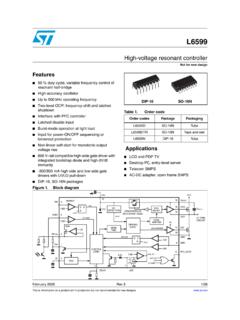
High-voltage resonant controller - STMicroelectronics
www.st.comHigh-voltage resonant controller Features 50 % duty cycle, variable frequency control of resonant half-bridge High-accuracy oscillator Up to 500 kHz operating frequency Two-level OCP: frequency-shift and latched shutdown Interface with PFC controller Latched disable input Burst-mode operation at light load

USB Power Delivery and Type-C - STMicroelectronics
www.st.comSeries-resonant half -bridge topology • Self adjusting adaptive dead time • Anti-capacitive mode protection • Two-level OCP • Frequency shift • Immediate shutdown • Safe-start procedure • Burst-mode operation at light load • Brown-out protection • Interface with PFC controller. Features. Benefits • High efficiency:

ON Semiconductor Is Now
www.onsemi.comcurrent is sensed at negative DC output line as a voltage drop over 300 shunt, amplified by special current sensing amplifier NCS210. Since controller board sits on secondary side, primary side input voltage information has to be insulated in reasonable way. Simple voltage to current converter at primary side is

AVR446: Linear speed control of stepper motor
ww1.microchip.comThe resonant speed will depend on the driving scheme of the stepper motor and the load. Figure 2-3. Torque vs. speed Τ ω Resonant Speed Maximum torque is achieved at low speeds, and this is an advantageous in many applications. 2.2 Fundamental stepper motor equations To create rotational motion in a stepper motor, the current thru the ...
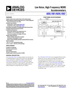
Low Noise, High Frequency MEMS Accelerometers Data Sheet ...
www.analog.comQuiescent Supply Current 1.0 1.15 1.0 1.15 mA Standby Current . 225 . 285 . 225 . 285 : µA . Standby Recovery Time (Standby to Measure Mode) Output settled to 1% of final value <50 <50 . µs . Turn On Time
LLC Converter Design Note - Mouser Electronics
www.mouser.comResonant frequency (7) r r m L L L m Ratio of total primary inductance to resonant inductance (8) The resonant gain will have a general shape as shown below in Figure 3.1: Figure 3.1: Shape of the resonant gain at different values of Q Gain is 1 at Fx=1 and lower for Fx>1. Assuming Q<1, gain is higher for Fx<1. The minimum frequency of