Search results with tag "Resonant"

Oscillator Circuits
sites.science.oregonstate.eduCrystal Resonant Frequencies The crystal has two resonant frequencies: Series resonant: RLC determine the resonant frequency. The crystal has a low impedance. Parallel resonant:RL and CM determine the resonant frequency. The crystal has a high impedance. The series and parallel resonant frequencies are very close, within 1% of each other.

NCP1397 - High Performance Resonant Mode Controller with ...
www.onsemi.comHigh Performance Resonant Mode Controller with Integrated High-Voltage Drivers The NCP1397 is a high performance controller that can be utilized in half bridge resonant topologies such as series resonant, parallel resonant and LLC resonant converters. It integrates 600 V gate drivers, simplifying layout and reducing external component count.
Topology Investigation for Front End DC/DC Power ...
vtechworks.lib.vt.eduLLC resonant topology is found to posses the desired characteristic. From comparison, LLC resonant converter could reduce the total loss by 40% at same switching frequency. With doubled switching frequency, efficiency of LLC resonant converter is still far better than PWM converters. To design the power stage of LLC resonant converter, DC ...

My Top Five Backyard Multi-Band Wire HF Antennas
www.qsl.netresonant 1/2-wavelength dipole. So let's review its characteristics. The 1/2-Wavelength Center-Fed Resonant Dipole The antenna that we loosely call the dipole is actually a 1/2-wavelength center-fed resonant or nearly resonant dipole. We usually construct it from AWG #14 or #12 copper or copperweld wire for the
LLC Resonant Converter for Battery Charging Application
irphouse.comLLC Resonant Converter for Battery Charging Application G. Subitha Sri and Dr. D. Subbulekshmi School of Electrical Engineering, VIT University, Chennai ... using PSIM software and the output voltage is regulated with the help of PI controller as a feedback path. In Section II operation of LLC resonant converter is discussed.

NCP13992 - Current Mode Resonant Controller with ...
www.onsemi.com5 LLC FB LLC feedback input Defines operating frequency based on given load conditions. Activates skip mode operation under light load conditions. 6 LLC CS LLC current sense input Senses divided resonant capacitor voltage to perform on−time modulation, out of resonant switching protection, over−current protection and secondary side

什么是软开关技术 - tup.tsinghua.edu.cn
www.tup.tsinghua.edu.cn全谐振变换器,也称为谐振变换器(Resonant Converters)。这种变换器实际上是 负载谐振式变换器,按照元件的谐振方式,分为串联谐振变换器(Series Resonant Converters,SRCs)和并联谐振变换器(Parallel Resonant Convers,PRCs)两种。按负载与 谐振电路的连接关系,谐振变换器也可以分为 …
TEA19161 and TEA19162 controller ICs - NXP
www.nxp.comThe TEA1916 is a fully digital controller for high-efficiency resonant power supplies. It is a 2-chip combo, which includes the TEA19161 resonant/LLC controller and the TEA19162 PFC controller. Together with the TEA1995T dual SR controller, a complete resonant power supply can be built, which is easy to design and has a very low component count.

LLC Resonant Converter Using MC56F83783 - NXP
www.nxp.comcan be used to analyze the LLC resonant converter, the input-to-output voltage gain can be obtained as: Where, • • • • • fsw is the operating frequency. Figure 2 shows the input-to-output gain varies with fn under certain m and Qe. NXP Semiconductors System description LLC Resonant Converter Using MC56F83783, Rev. 0, 10/2019 ...
A Mathematical Guideline for Designing an AC-DC LLC ...
gansystems.comA. LLC Resonant Converter Voltage Gain Review The half-bridge LLC resonant converter prototype is shown in Fig. 1. The operating frequency range of the LLC PFC is defined as fp ≤ fs ≤ fr, where below-resonance operation is preferred to ensure the inductive impedance characteristics of the LLC resonant tank, so that the soft
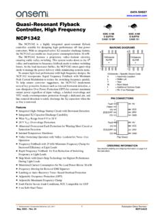
NCP1342 - Quasi-Resonant Flyback Controller, High Frequency
www.onsemi.comQuasi-Resonant Flyback Controller, High Frequency NCP1342 The NCP1342 is a highly integrated quasi−resonant flyback controller suitable for designing high−performance off−line power converters. With an integrated active X2 capacitor discharge feature, the NCP1342 can enable no−load power consumption below 30 mW.

DC/DC Power Conversion for Datacenter, Open Compute …
media.monolithicpower.cominductor-capacitor) is a resonant topology comprised of two inductors and one capacitor. It allows for zero-current switching of the main switches, thereby dramatically lowering switching losses and boosting efficiency. Figure 4 shows an example of an LLC resonant converter.
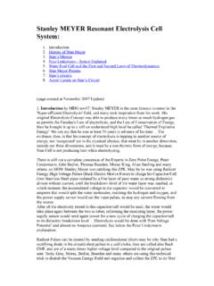
Stanley MEYER Resonant Electrolysis Cell System : (page cre
www.rivendellvillage.orgapparently possesses a dielectric constant of about 5--- to produce a parallel resonant circuit. This is excited by a high power pulse generator which, together with the cell capacitance and a rectifier diode, forms a charge pump circuit. High frequency pulses build a rising staircase DC potential across the electrodes of the

Zero Voltage Switching Resonant Power Conversion
www.ti.comcycle where the switch current is zero, facilitat-3-329 ing zero current, hence zero power switching. And while true, two obvious concerns can impede the quest for high efficiency operation with high voltage inputs. By nature of the resonant tank and zero current switching limitation, the peak switch current is significantly higher than its square
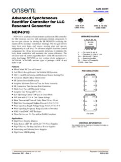
NCP4318 - Advanced Synchronous Rectifier Controller for ...
www.onsemi.comRectifier Controller for LLC Resonant Converter NCP4318 NCP4318 is an advanced synchronous rectification (SR) controller for LLC resonant converter with minimum external components. It has two gate drivers for driving the SR MOSFETs rectifying the ... • Low Operating Current (100 A) in Green Mode
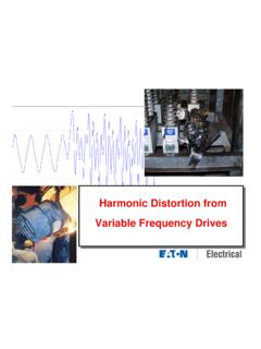
Harmonic Distortion from Variable Frequency Drives
ewh.ieee.org• PFCC’s change the resonant frequency of the distribution system – Depends on the size of the caps and the impedance of the system • Can magnify any existing harmonics Parallel Resonant Frequencies for Various Capacitor Sizes 0 50 100 150 200 250 300 350 400 450 500 0 100 200 300 400 500 600 0 5 10 15 20 25 Harmonic Order Capacitor Size
LLC Converter Design Note - Mouser Electronics
www.mouser.comSince the resonant converter gain is expressed with respect to sinusoidal in- and out-puts, both need conversion, which results in a total gain factor of , 1 2 1 G HB | G FB | (2) For Half-bridge or fullbridge front-ends respectively. The last gain-term is the one for the resonant network: ( 2 2 2 2 2 2 2 1 1 ( , , ) Fxm Q Fx m K Q m Fx 3)
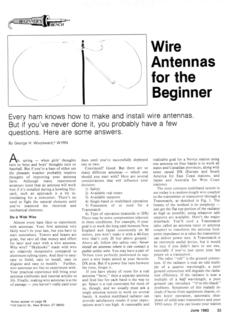
Wire Antennas for the Beginner - ARRL - Home
www.arrl.orgthe resonant frequency, of course, but sharpening the apex angle will lower both the resonant frequency and the radiation resistance. The Novice subbands are only 50- and 100-kHz wide, so it should be possible to achieve an SWR of 1.5:1 or less across this segment. Any transmitter should be happy with that. What if everything is cut right and it
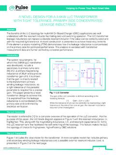
A NOVEL DESIGN FOR A 3.6KW LLC TRANSFORMER WITH …
www.pulseelectronics.comIntroduction The LLC Converter The LLC Transformer The benefits of the LLC topology for multi-KW On Board Charger (OBC) applications are well understood with the resonant inductor facilitating zero volt switching operation. The LLC transformer leakage inductance can replace a discrete resonant inductor if the value can be correctly sized and

EXAMPLE PROBLEMS AND SOLUTIONS A-8-1. a is A-6-8.) of a s
eee.sutech.ac.irSolution. Qurc 8-92 shows the Bodc diagram for- the system. The resonant peak value is np- proximately 3.5 dB. (Note that, in the abscnce of n zero. thc second-order system with [ ;- 0.7 \\ill not exhibit a resonant peak; ho\vevcr, the presence of a closed-loop zero will cause such a peak.,) Example Problems and Solutions

AVR446: Linear speed control of stepper motor
ww1.microchip.comThe resonant speed will depend on the driving scheme of the stepper motor and the load. Figure 2-3. Torque vs. speed Τ ω Resonant Speed Maximum torque is achieved at low speeds, and this is an advantageous in many applications. 2.2 Fundamental stepper motor equations To create rotational motion in a stepper motor, the current thru the ...

NCP1380 - Quasi-Resonant Current-Mode Controller for …
www.onsemi.comHigh-Power Universal Off-Line Supplies The NCP1380 hosts a high−performance circuitry aimed to powering quasi−resonant converters. Capitalizing on a proprietary ... This pin observes the HV rail and protects the circuit in case of low main conditions. It also offers a way to latch the
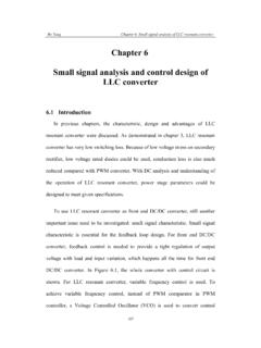
Ch6. Small Signal Analysis of LLC Resonant Converter
vtechworks.lib.vt.edusimulated in two hours. With simulation method, a SRC was analyzed. The results were shown in Appendix C. 6.3.1 Small signal characteristic of LLC resonant converter With extended describing function method, the characteristic in region 1 is shown in Figure 6.8. It is a three poles and one zero system.
Zero Voltage Switching - Texas Instruments
www.ti.comResonant Power Conversion Bill Andreycak ing zero current, hence zero power switching. And while true, two obvious concerns can in1pede the quest for high efficiency operation with high voltage inputs. By nature of the resonant tank and zero …

ON Semiconductor Is Now
www.onsemi.comrange of output voltages makes resonant tank design more complex. Furthermore, with certain small modifications also other converter topologies, full bridge phase shifted converter for example, could be tested as well. Power Stage Target output power level at around 10 kW and LLC topology indicates that full bridge power stage is the

Quality factor, Q - UC Santa Barbara
web.ece.ucsb.eduIf we consider an example of a series resonant circuit. At resonance, the reactances cancel out leaving just a peak voltage, Vpk, across the loss resistance, R. Thus, Ipk = Vpk/R is the maximum current which passes through all elements. Then, R RC …
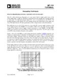
MT-101: Decoupling Techniques - Analog Devices
www.analog.comfrequency range, dc bias current, number of turns, size, shape, and temperature. ... (equivalent series resistance, or ESR), appears in series with the capacitor and represents the ... Figure 4: Impedance of Various 100µF Capacitors The self-resonant frequency of the capacitor is the frequency at which the reactance of the capacitor (1/ωC ...
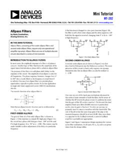
Mini Tutorial - Analog Devices
www.analog.comthis series of mini tutorialsto build the filter, but be aware of whether the BP inverts the phase or not. In addition, be aware ... resonant frequency should be at least 20 dB. Also, since there is a capacitor in the feedback network, a current feedback amplifier is probably not appropriate.
Designing DC/DC converters based on ZETA topology
www.ti.comconverter topology provides a positive output voltage from ... voltage. The ZETA converter also needs two inductors and a series capacitor, sometimes called a flying capacitor. Unlike the SEPIC converter, which is configured with a standard boost converter, the ZETA converter is config- ... be greater than the resonant frequency of L1b and C C so

Frequency Response of Thin Film Chip Resistors
www.vishay.comobserved series inductance to the skin effect or surface impedance used in waveguide and resonant cavity applications. (2)(4)(5)(9)(10) These papers note that the increasing impedance is proportional to the square root of the frequency. (2)(4) The skin effect however does not support
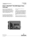
Fisher FIELDVUE DVC2000 Digital Valve Controller
www.emerson.comController The FIELDVUE DVC2000 digital valve controller is simple to use, compact, and designed for easy mounting. It converts a 4-20 mA input signal into a ... resonant frequency search is performed on all three axes. The instrument is subjected to the ISA specified 1/2 hour endurance test at each major resonance,
EXPERIMENT #1 STUDY OF RC AND RL CIRCUITS
www.iium.edu.myFind the resonant frequency using equation given in the before and compare it to the experimental value in both cases. Plot the voltage response of the circuit and obtain the bandwidth from the half-power frequencies using equation. ECE Lab III ECE 2201 SEMESTER II, 2011/2012 By Sheroz Khan

Snubber circuit design methods - Rohm
fscdn.rohm.comis bulk capacitor placed in parallel with input HVdc-PGND. During the turn off of LS, surge voltage occurs in drain-source of LS by resonant phenomenon between L MAIN and parasitic capacitance of the MOSFET C OSS ( C DS + DG). The maximum voltage V DS_SURGE is as shown in (1). Where V HVDC is the applied voltage on HVdc terminal and R OFF
EMI Noise Reduction Techniques for High Frequency Power ...
vtechworks.lib.vt.edutransformer LLC converter, the inter-winding capacitor is very large and will cause severe CM noise problem. By adding shielding layer, CM noise has been greatly reduced. Although flyback and LLC resonant converter are used as examples to demonstrate the …
Chapter 5 Capacitance and Dielectrics
web.mit.eduresistors, filtering out unwanted frequency signals, forming resonant circuits and making frequency-dependent and independent voltage dividers when combined with resistors. Some of these applications will be discussed in latter chapters. Figure …
Alternating Voltage and Current
www.oakton.eduAn important application is a resonant circuit with L and C that is tuned to a particular frequency. 15-2: Alternating-Voltage Generator ... The negative half-cycle of applied voltage is as useful as the positive half-cycle in producing current.

Precision, Miniature MEMS IMU Data Sheet ADIS16505
www.analog.comCONTROLLER POWER MANAGEMENT CS SCLK DIN DOUT GND DR VDD SYNC RST SPI SELF TEST INPUT/OUTPUT OUTPUT DATA REGISTERS USER CONTROL REGISTERS CALIBRATION AND FILTERS ADIS16505 CLOCK TRIAXIAL ... Sensor Resonant Frequency X-axis and y-axis 2.4 kHz Z-axis 2.2 kHz TEMPERATURE SENSOR Scale Factor Output = …
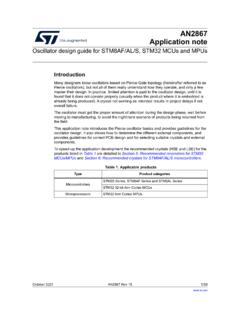
AN2867 Application note - STMicroelectronics
www.st.comis the anti-resonant frequency when impedance Z tends to infinity. Using equation (1), it is expressed as follows: Fa Fs 1 Cm C0 = + -----The region delimited by F. s. and F. a. is usually called the area of parallel resonance (shaded area in . Figure 2). In this region, the crystal operates in parallel resonance and behaves as
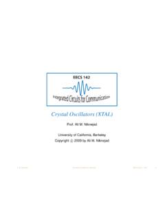
Crystal Oscillators (XTAL) - University of California ...
rfic.eecs.berkeley.eduSeries and Parallel Mode C 0 L 1 C 1 R 1 C 0 L 1 R 1 low resistance high resistance Due to the external physical capacitor, there are two resonant modes between a series branch and the capacitor. In the series mode ωs, the LCR is a low impedance (“short”). But beyond this frequency, the LCR is an equivalent inductor that resonates
Series 3000 Cooling Tower
baltimoreaircoil.com43 Resonant Speed Identification Procedure PART 8 New Field Connections for TriArmor® Corrosion Protection System Cold Water Basin 45 Installation Instructions OPERATION & MAINTENANCE » SERIES 3000 COOLING TOWER 1 WWW.BALTIMOREAIRCOIL.COM. 2 WWW.BALTIMOREAIRCOIL.COM DANGER

SIX MAIN COMPONENTS OF MRI SYSTEM
www.aheconline.comresonant frequency. MRI Core 12 PULSE SEQUENCE CONTROLLER The pulse sequence controller is responsible for the timing and performance of each system component. The pulse sequence controller dictates when and how much gradient power is needed to vary the magnetic field and spatially encode the MR signal.

Small Magnetic Loop Antenna Project
qrpbuilder.comThese antennas are high-Q resonant circuits. Many kilovolts can be present across the capacitor, and produce concentrated electro-magnetic radiation even at low power levels. For safety, maintain a minimum of 6 feet away from the antenna, while ... Motor controller, direction and speed www.mpja.com, #16816MD, 24v, 40 rpm gearmotor.
Analysis and Design of Input Filter for DC-DC Circuit - TI.com
www.ti.comSimple LC passive filters are among the common filters for DC-DC converters. They can attenuate the high frequency noise from the power supply and can also suppress the switching noise to go back to the power supply. If LC filter is not well damped, the frequency response will peak near resonant frequency, which means
Introduction to Microstrip Antennas - University of Houston
courses.egr.uh.eduHowever, the Q of the resonant cavity mode also increases, making the patch currents stronger at resonance. These two effects cancel, allowing the patch to radiate well even for thin substrates (though the bandwidth decreases). 31 A microstrip antenna can radiate well, even with a …

The TEA1995T can also be used in multi-output ... - NXP
www.nxp.comThe TEA1995T is intended for resonant power supplies. In such applications, it can drive two external synchronous rectifier MOSFETs for the rectification of the voltages on the two secondary windings of the transformer. These MOSFETs replace diodes. It can be used in all power supplies requiring high efficiency: • Adapters

LT8304 - 100VIN Micropower No-Opto Isolated Flyback ...
www.analog.comn Low Quiescent Current: n 116µA in Sleep Mode n 390µA in Active Mode n Quasi-Resonant Boundary Mode Operation at Heavy Load n Low Ripple Burst Mode® Operation at Light Load n Minimum Load < 0.5% (Typ) of Full Output n No Transformer Third Winding or Opto-Isolator Required for Output Voltage Regulation n Accurate EN/UVLO Threshold and Hysteresis

Construction Details 49:1 Un-Un For End-Fed Resonant …
qsl.net2. At the end that will connect to the Balun, pass approximately 1-1/2 foot through holes at one end of an insulator and tie with a couple throws of a knot. Strip off about 1/4” of insulation and then Crimp and then solder one of the crimp terminals on the free end. This will connect to the RED terminal output of your Balun. 3.
Similar queries
Resonant, Series resonant, SERIES, LLC resonant, Top Five Backyard Multi-Band Wire HF Antennas, Controller, Parallel resonant, Frequency, Power Conversion for Datacenter, Open Compute, An LLC resonant, Zero Voltage Switching Resonant Power Conversion, Cycle, Switching, Advanced Synchronous Rectifier Controller for, Current, Mode, Mouser Electronics, Conversion, Wire Antennas for the Beginner, Introduction, NCP1380 - Quasi-Resonant Current-Mode Controller for, Power, Signal Analysis of LLC Resonant Converter, Method, Characteristic, Zero Voltage Switching, Texas Instruments, Analog Devices, Capacitors, Converter, Frequency Response of Thin Film Chip Resistors, FIELDVUE DVC2000 digital valve controller, Half, Snubber circuit design methods, Parallel, Chapter 5 Capacitance and Dielectrics, AN2867 Application note, XTAL, Magnetic Loop, Converters, For End-Fed Resonant, Balun, Your Balun