Parallel Resonant
Found 10 free book(s)
RLC Resonant Circuits - University of Cambridge
mlg.eng.cam.ac.uk3 Parallel Circuit Figure 5 shows a parallel resonant RLC circuit. It is the ‘dual’ of the series circuit in that the voltage and current exchange roles. This means that the circuit has a current gain rather than a voltage gain and that the impedance is 3.

Quality factor, Q
web.ece.ucsb.eduWhen a resonant circuit is connected to the outside world, its total losses (let’s call them RP or GP) are combined with the source and load resistances, RS and RL. For example, Here is a parallel resonant circuit (C,L and RP)connected to the outside. The total Q of this circuit is called the loaded Q or QL and is given by
Stanley MEYER Resonant Electrolysis Cell System : (page cre
www.rivendellvillage.orgapparently possesses a dielectric constant of about 5--- to produce a parallel resonant circuit. This is excited by a high power pulse generator which, together with the cell capacitance and a rectifier diode, forms a charge pump circuit. High frequency pulses build a rising staircase DC potential across the electrodes of the
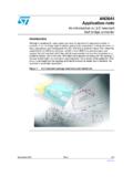
An introduction to LLC resonant half-bridge converter
www.st.comparallel to one C, generates the LCC resonant inverter commonly used in electronic lamp ballast for gas-discharge lamps. Its dual configuration, using two inductors and one capacitor, with the load connected in parallel to one L, generates the LLC inverter. As previously stated, for any resonant inverter there is one associated DC-DC resonant

Agilent Basics of Measuring the Dielectric Properties of ...
academy.cba.mit.eduResonant cavity .....25 Parallel plate .....27 Comparison of methods ... across a parallel plate capacitor, more charge is stored when a dielectric material is between the plates than if no material (a vacuum) is between the plates. The dielectric material increases the storage capacity of the capacitor
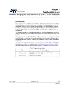
AN2867 Application note - STMicroelectronics
www.st.comis the anti-resonant frequency when impedance Z tends to infinity. Using equation (1), it is expressed as follows: Fa Fs 1 Cm C0 = + -----The region delimited by F. s. and F. a. is usually called the area of parallel resonance (shaded area in . Figure 2). In this region, the crystal operates in parallel resonance and behaves as

Snubber circuit design methods - Rohm
fscdn.rohm.comis bulk capacitor placed in parallel with input HVdc-PGND. During the turn off of LS, surge voltage occurs in drain-source of LS by resonant phenomenon between L MAIN and parasitic capacitance of the MOSFET C OSS ( C DS + DG). The maximum voltage V DS_SURGE is as shown in (1). Where V HVDC is the applied voltage on HVdc terminal and R OFF
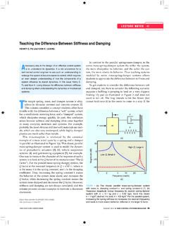
Teaching the Difference Between Stiffness and Damping
hfu.mech.utah.eduFactor”). For the parallel mass-spring-damper system, the Q factor at the resonant frequency is Q m. k c/ , where m is the mass, k is the spring constant, and c is the damping coefficient. Thus, increasing the spring constant k makes the behavior of the system more elastic and increases the Q factor, while decreasing the spring constant makes the
Alternating Voltage and Current
www.oakton.eduAn important application is a resonant circuit with L and C that is tuned to a particular frequency. 15-2: Alternating-Voltage Generator ... parallel branches is the same as the applied voltage.
Chapter 5 Capacitance and Dielectrics
web.mit.eduresistors, filtering out unwanted frequency signals, forming resonant circuits and making frequency-dependent and independent voltage dividers when combined with resistors. Some of these applications will be discussed in latter chapters. Figure …