Transcription of Alternating Voltage and Current
1 Alternating Voltage and Current Topics Covered in Chapter 15 15-1: Alternating Current Applications 15-2: Alternating - Voltage Generator 15-3: The Sine Wave 15-4: Alternating Current 15-5: Voltage and Current Values for a Sine Wave 15-6: Frequency Chapter 15 2007 The McGraw-Hill Companies, Inc. All rights reserved. Topics Covered in Chapter 15 15-7: Period 15-8: Wavelength 15-9: Phase Angle 15-10: The Time Factor in Frequency and Phase 15-11: Alternating Current Circuits with Resistance 15-12: Nonsinusoidal AC Waveforms 15-13: Harmonic Frequencies 15-14: The 60-Hz AC Power Line 15-15: Motors and Generators 15-16: Three-Phase AC Power McGraw-Hill 2007 The McGraw-Hill Companies, Inc. All rights reserved. 15-1: Alternating Current Applications A transformer can only operate with Alternating Current to step up or step down an ac Voltage . A transformer is an example of inductance in ac circuits where the changing magnetic flux of a varying Current produces an induced Voltage .
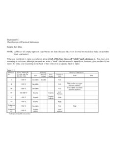
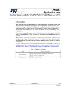
2 Capacitance is important with the changing electric field of a varying Voltage . The effects of inductance and capacitance depend on having an ac source. An important application is a resonant circuit with L and C that is tuned to a particular frequency. 15-2: Alternating - Voltage Generator Characteristics of Alternating Current Alternating Voltage and Alternating Current vary continuously in magnitude and reverse in polarity. One cycle includes the variations between two successive points having the same value and varying in the same direction. Frequency is measured in hertz (Hz). 15-2: Alternating - Voltage Generator The conductor loop rotates through the magnetic field to generate induced ac Voltage across open terminals. At the horizontal position, the loop does not induce a Voltage because the conductors do not cut across the flux. At the vertical position, conductors cut across the flux and produce maximum v.
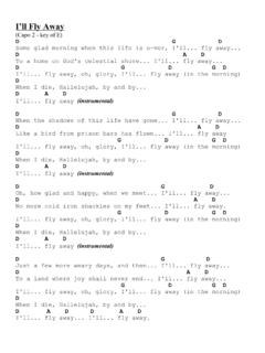
3 Each of the longer conductors has opposite polarity of induced Voltage . Copyright The McGraw-Hill Companies, Inc. Permission required for reproduction or display. Fig. 15-2: Loop rotating in magnetic field to produce induced Voltage v with Alternating polarities. (a) Loop conductors moving parallel to magnetic field results in zero Voltage . (b) Loop conductors cutting across magnetic field produce maximum induced Voltage . 15-2: Alternating - Voltage Generator The Cycle One complete revolution of the loop around the circle is a cycle. The half-cycle of revolution is called an alternation. 15-2: Alternating - Voltage Generator Copyright The McGraw-Hill Companies, Inc. Permission required for reproduction or display. Fig. 15-3: One cycle of Alternating Voltage generated by rotating loop. Magnetic field, not shown here, is directed from top to bottom, as in Fig. 15-2. The Voltage waveform shown in Fig. 15-3 is called a sine wave, sinusoidal wave , or sinusoid because the amount of induced Voltage is proportional to the sine of the angle of rotation in the circular motion producing the Voltage .
4 15-2: Alternating - Voltage Generator Angular Measure and Radian Measure The cycle of Voltage corresponds to rotation of the loop around a circle, so parts of the cycle are described in angles. The radian (rad) is an angle equivalent to A radian is the angular part of the circle that includes an arc equal to the radius r of the circle. A circle s circumference equals 2 r, so one cycle equals 2 rad. Copyright The McGraw-Hill Companies, Inc. Permission required for reproduction or display. Fig. 15-3(a). 15-2: Alternating - Voltage Generator Angular Measure and Radian Measure Angular Measurement Radian Equivalent Zero degrees Zero radians 360 2 rad 180 2 rad, or rad 90 rad, or /2 rad 270 (180 + 90 ) rad + /2 rad = 3 /2 rad 15-2: Alternating - Voltage Generator Amplitude 0 0 90 180 270 360 2 rad rad /2 rad 0 rad 3/2 rad Copyright The McGraw-Hill Companies, Inc. Permission required for reproduction or display.
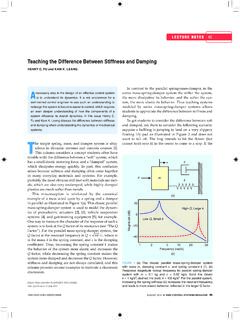
5 Angular Measure and Radian Measure 15-3: The Sine Wave The Voltage waveform pictured here is called a sine wave, sinusoidal wave, or sinusoid. The induced Voltage is proportional to the sine of the angle of rotation in the circular motion producing the Voltage . Copyright The McGraw-Hill Companies, Inc. Permission required for reproduction or display. Fig. 15-1(a): Waveform of ac power-line Voltage with frequency of 60 Hz. Two cycles are shown. Oscilloscope readout. 15-3: The Sine Wave With a sine wave, the induced Voltage increases to a maximum at 90, when the loop is vertical, just as the sine of the angle of rotation increases to a maximum at 90 . The instantaneous value of a sine-wave Voltage for any angle of rotation is expressed in the formula: v = VM sin (theta) is the angle sin = the abbreviation for sine VM = the maximum Voltage value v = the instantaneous value of Voltage at angle . 15-3: The Sine Wave Characteristics of the Sine-Wave AC Waveform: The cycle includes 360 or 2 rad.
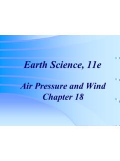
6 The polarity reverses each half-cycle. The maximum values are at 90 and 270 . The zero values are at 0 and 180 . The waveform changes its values the fastest when it crosses the zero axis. The waveform changes its values the slowest when it is at its maximum value. 15-4: Alternating Current When a sine wave of Alternating Voltage is connected across a load resistance, the Current that flows in the circuit is also a sine wave. The sine wave frequency of an Alternating Voltage is the same as the Alternating Current through a series connected load resistance. 15-4: Alternating Current Copyright The McGraw-Hill Companies, Inc. Permission required for reproduction or display. Fig. 15-5: A sine wave of Alternating Voltage applied across R produces a sine wave of Alternating Current in the circuit. (a) Waveform of applied Voltage . (b) AC circuit. Note the symbol for sine-wave generator V. (c) Waveform of Current in the circuit.
7 15-4: Alternating Current After the first half-cycle, polarity reverses and Current flows in the opposite direction. The negative half-cycle of applied Voltage is as useful as the positive half-cycle in producing Current . The direction does not matter in the application. The motion of electrons against resistance produces power dissipation. Only v and i waveforms can be compared. 15-5: Voltage and Current Values for a Sine Wave The following specific magnitudes are used to compare one wave to another: Peak value: maximum value VM or IM. This applies to the positive or negative peak. Peak-to-peak: usually, but not always, double the peak value, as it measures distance between two amplitudes. Average value: Arithmetic average of all values in one half-cycle (the full cycle average = 0). Root-Mean-Square (RMS) or Effective Value: Relates the amount of a sine wave of Voltage or Current to the DC values that will produce the same heating effect.
8 15-5: Voltage and Current Values for a Sine Wave The average value is peak value. The rms value is peak value. The peak value is rms value. The peak-to-peak value is rms value. 15-5: Voltage and Current Values for a Sine Wave Copyright The McGraw-Hill Companies, Inc. Permission required for reproduction or display. Fig. 15-6: Definitions of important amplitude values for a sine wave of Voltage or Current . 15-5: Voltage and Current Values for a Sine Wave 120 V 120 V + 100 100 Vrms is the effective value. The heating effect of these two sources is identical. Same power dissipation The default sine wave ac measurement is Vrms . 15-6: Frequency Frequency ( f ) is the number of cycles per second. Cycle is measured between two successive points having the same value and direction. One cycle per second is 1 Hz. 15-6: Frequency Amplitude 0 Time 1 sec f = 2 Hz sec Sine Wave Frequency (two cycles shown) Copyright The McGraw-Hill Companies, Inc.
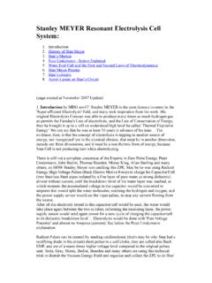
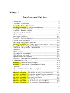
9 Permission required for reproduction or display. 15-7: Period Period (T) is the time per cycle. T = 1/f f = 1/T The higher the frequency, the shorter the period. 15-7: Period Amplitude 0 Time s f = 1/T = 1/.0167 = 60 Hz T Period (T) Copyright The McGraw-Hill Companies, Inc. Permission required for reproduction or display. 15-9: Phase Angle Phase angle ( ) is the angular difference between the same points on two different waveforms of the same frequency. Two waveforms that have peaks and zeros at the same time are in phase and have a phase angle of 0 . When one sine wave is at its peak while another is at zero, the two are 90 out of phase. When one sine wave has just the opposite phase of another, they are 180 out of phase. 15-9: Phase Angle Copyright The McGraw-Hill Companies, Inc. Permission required for reproduction or display. Fig. 15-10: Two sine-wave voltages 90 out of phase. (a) Wave B leads wave A by 90.
10 (b) Corresponding phasors VB and VA for the two sine-wave voltages with phase angle = 90 . The right angle shows quadrature phase. 15-9: Phase Angle Phase-Angle Diagrams Similar to vectors, phasors indicate the amplitude and phase angle of ac Voltage or Current . A vector quantity has direction in space, but a phasor angle represents a difference in time. The length of the phasor represents the amplitude of the waveform. The angle represents the phase angle of the waveform. 15-9: Phase Angle Phase-Angle Diagrams The phasor corresponds to the entire cycle of Voltage . The phase angle of one wave can be specified only with respect to another as a reference. Usually the reference phasor is horizontal. Copyright The McGraw-Hill Companies, Inc. Permission required for reproduction or display. Fig. 15-11: Leading and lagging phase angles for 90 . (a) When phasor VA is the horizontal reference, phasor VB leads by 90.