Transcription of Mini Tutorial - Analog Devices
1 Rev. 0 | Page 1 of 2 Mini Tutorial MT-202 One Technology Way P. O . Box 9106 Norwood, MA 02062-9106, Tel: Fax: Allpass Filters by Hank Zumbahlen, Analog Devices , Inc. IN THIS MINI Tutorial Allpass filters, consisting of first-order allpass filters and second-order allpass filters, require only one operational amplifier (op amp). Allpass filters are one of multiple discrete circuits described in a series of mini tutorials. INTRODUCTION TO ALLPASS FILTERS In most cases, the amplitude response of a filter is of primary concern. Another type of filter that leaves the amplitude of the signal intact, but introduces phase shift is called an allpass filter.
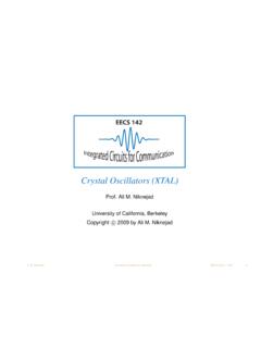
2 The purpose of this filter is to add phase shift (delay) to the response of the circuit. The amplitude of an allpass is unity for all frequencies. The phase response, however, changes from 0 to 360 (for a 2-pole filter) as the frequency is swept from 0 to infinity. One use of an allpass filter is to provide phase equalization, typically in pulse circuits. It also has application in single side band, suppressed carrier (SSB-SC) modulation circuits. The transfer function of an allpass filter is 20022002)( + ++ =sQssQssH (1) Note that an allpass transfer function can be synthesized as HAP = HLP HBP + HHP = 1 2 HBP (2) FIRST-ORDER ALLPASS The general form of a first-order allpass filter is shown in Figure 1.
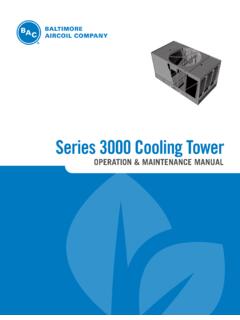
3 If the function is a simple RC high pass (Figure 1A), the circuit has a phase shift that goes from 180 at 0 Hz. and 0 at high frequency. It is 90 at = 1/RC. The resistor may be made variable to allow adjustment of the delay at a particular frequency. If the function is changed to a low-pass function (Figure 1B), the filter is still a first-order allpass and the delay equations still hold, but the signal is inverted, changing from 0 at dc to 180 at high frequency. Figure 1. First-Order Allpass Filter SECOND-ORDER ALLPASS A second-order allpass circuit shown in Figure 2 was first described by Delyiannis (see the References section).
4 The main attraction of this circuit is that it only requires one op amp. Remember also that an allpass filter can also be realized as 1 2 B P. Figure 2. Second-Order Allpass Filter One may use any of the band-pass realizations discussed in this series of mini tutorials to build the filter, but be aware of whether the BP inverts the phase or not. In addition, be aware that the gain of the BP section must be 2. To this end, the dual amplifier band-pass filter (DABP) structure is particularly useful, since its gain is fixed at 2. To select an op amp, we primarily need to concern ourselves with the bandwidth.
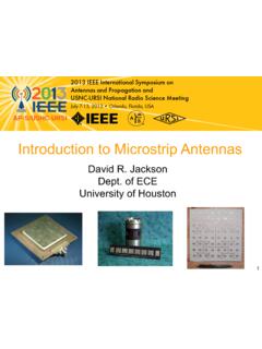
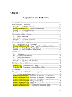
5 The rule of thumb is that the open-loop gain of the amp at the resonant frequency should be at least 20 dB. Also, since there is a capacitor in the feedback network, a current feedback amplifier is probably not appropriate. Figure 3 and Figure 4 summarize design equations for various active filter realizations. In all cases, H, o, Q, and are given, taken from the design tables. R(A)CR1R1 OUTIN(B)CR1RR1 OUTIN10400-002R4R2 OUTR1 CCR3IN10400-003MT-202 Mini Tutorial Rev. 0 | Page 2 of 2 FIRST-ORDER ALLPASS DESIGN EQUATIONS RCsRCsVVINO11+ = Figure 3. ( ) = FRCTanShiftPhase 221 ()1222+=FRCRCD elayGroup Delay at dc = 2 RC Given a phase shift of at a frequency = F =22 TANFRC Figure 4 design is the same as Figure 3 except the sign of the phase changes.
6 Figure 4. SECOND-ORDER ALLPASS DESIGN EQUATIONS 20022002 + ++ QssQss Figure 5. 22222112221122 CRRCRssCRRCRssVVINO+ ++ = To design the filter, choose C. k = 2 F0C kQR22= QkR211= 13RR= 24QR= REFERENCES Delyiannis, T. High-Q Factor Circuit with Reduced Sensitivity, Electronic Letters, Volume 4, December 1968. p. 577. Zumbahlen, Hank. Linear Circuit Design Handbook. Elsevier. 2008. ISBN: 978-7506-8703-4. REVISION HISTORY 4/12 Revision 0: Initial Version RR1CR1 OUTIN10400-003CR1RR1 OUTIN10400-005R4R2 OUTR1 CCR3IN10400-006 2012 Analog Devices , Inc. All rights reserved.
7 Trademarks and registered trademarks are the property of their respective owners. MT10400-0-4/12(0)